Air brake hose support

a technology of air brake hose and support strap, which is applied in the direction of machine support, braking system, surface layering apparatus, etc., can solve the problems of metal clips that are difficult to open and close, metal clips that are difficult to apply or remove, and wire supports which pose safety risks, etc., to achieve easy adjustment, little or no elongation, and easy grip

Active Publication Date: 2010-12-14
PENNSY CORP
View PDF9 Cites 8 Cited by
  • Summary
  • Abstract
  • Description
  • Claims
  • Application Information

AI Technical Summary

Benefits of technology

[0018]The present invention provides a solution to the problems identified above by utilizing an ergonomically designed strap which does not use a metallic clip arrangement but still simplifies application problems substantially, providing for easy installation and adjustment of the strap length.
[0021]The strap includes a multiplicity of spaced adjustment apertures extending in a line running from one end of the strap to approximately half way to the other. Each aperture may include a ridge around it to provide easy alignment of the collar and strap pin for insertion of the strap pin into the selected adjustment aperture. A further locating feature is a flat ridge or alignment groove which runs the length of the apertures. A corresponding flat or complementary alignment feature on the bore of the collar helps align the through hole in the collar with the apertures in the strap for insertion of the strap pin through the collar and aperture of the strap.
[0023]In preferred form, the strap, collar, strap pin and clevis pin are made of a urethane but can be made from epoxy, silicone, nylon or equivalent polymer material or polymer reinforced material which is flexible and weather resistant. The preferred material should also be resistant to ultraviolet rays and exhibit little or no elongation set. Should a strap need adjusting in the field for whatever reason, a worker can easily make the adjustment without removal of the strap from the coupler aperture and without use of any tools. Locating ridges molded over the apertures make the strap easily gripped by the gloved hand of a worker.

Problems solved by technology

Failure to maintain railcar air hoses at a proper height above the rail structure is a significant cause of unintended air hose coupling separation leading to emergency braking and stopping of the train and sometimes even derailment obviously, emergency braking is a cause of time-consuming and, thus, costly train delays as a crew member must walk the length of the train looking for the cause, and if it is found that there is an uncoupled air hose, the crew member must reconnect the couplings before returning to the engine.
Although these assemblies are effective in supporting the end of the air hose, the clips are difficult to open and close and almost impossible to apply or remove if the worker is wearing the required work gloves.
In addition, it has been noted that the metal clips can become damaged in service through the action of the coupler and / or as a result of the air hose flailing when the air is discharged from it following air hose separation.
Other examples of prior art air hose supports include chains which do not provide any give or shock absorbance, and wire supports which pose a safety risk when the wire frays and also does not provide any cushioning.

Method used


Image

  • Air brake hose support
  • Air brake hose support
  • Air brake hose support

Examples


embodiment 50

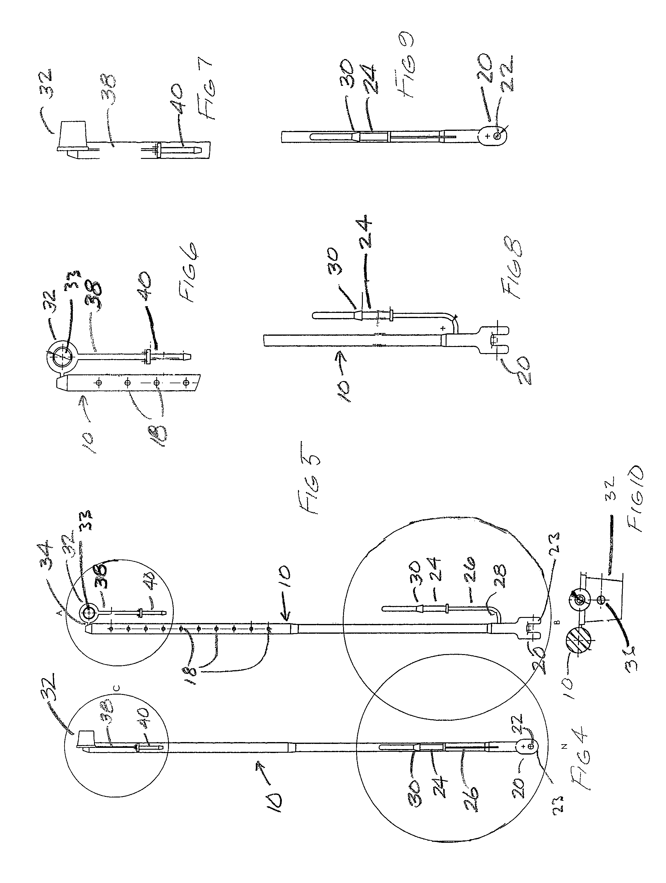
[0051]FIG. 11 illustrates and alternate embodiment 50 of the suspension device according to the invention. In device 50, strap 10 has a plurality of ridges 52 positioned in spaced relation along a portion of the strap coinciding with the apertures 18. Each ridge 52 surrounds a respective aperture 18 and facilitates alignment of a selected aperture and the through hole 36 in the collar 32. This allows the strap pin 40 to be readily inserted to lock the collar in a desired position on the strap 10.

[0052]Suspension device 50 may also have an alignment surface in the form of a flat surface 54 as shown in detail in FIG. 12. The flat surface 54 may be positioned on the ridges 52 as shown or, if the ridges are absent, be positioned on the circumference of the strap. Flat surface 54 engages a complementary flat surface 56 positioned on the bore 33 of the collar 32 as shown in FIG. 13. Engagement of the flat surfaces between the strap and the collar bore ensures that the strap is properly or...

embodiment 58

[0053]FIG. 14 shows another device embodiment 58 wherein the strap 10 has an alignment surface comprising a groove 60 that extends lengthwise along the strap in the region where apertures 18 are located. Groove 60 cooperates with a projection 62 within bore 33 of collar 32 to properly orient the collar and the strap so that the through hole 36 aligns with apertures 18 allowing insertion of strap pin 40. It is understood that the positions of the groove and projection could be reversed, i.e., the groove could be within the bore 33 of the collar and the projection could extend lengthwise along the strap 10.

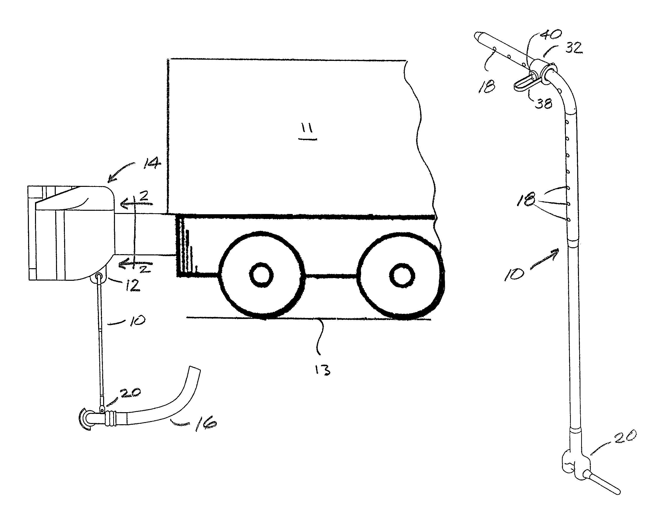
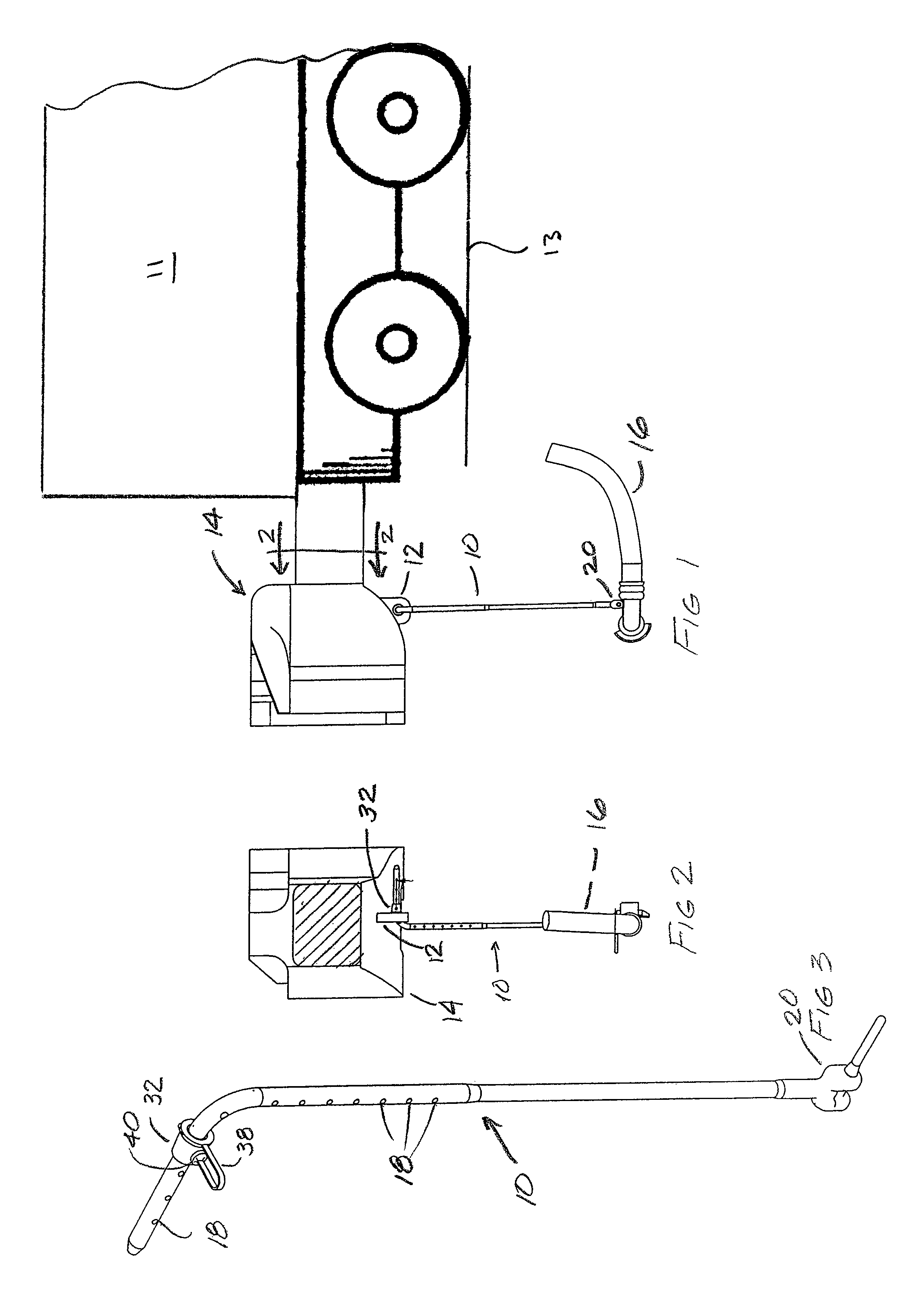
[0054]In summary, a flexible support for an air hose or like device is supplied with detachable coupling parts of non-metallic material preferably integrally provided. The use of metal fasteners or coupling elements can be avoided. The assembly is simple to manufacture and install on a rail car, is durable and easily adjusted or replaced in the field with little or no use of tools. ...


PUM

PropertyMeasurementUnit
lengthaaaaaaaaaa
lengthaaaaaaaaaa
heightaaaaaaaaaa

Abstract

A suspension device for supporting an air brake hose on a rail car is disclosed. The device includes a strap having a clevis at one end and a plurality of apertures in spaced relation lengthwise along the strap. A clevis pin is used to attach the clevis to a lug on the coupling of the air brake hose. The strap is inserted through a fitting on the coupler of the railcar and received within the bore of a collar. A through hole in the collar receives a strap pin that also extends through the apertures in the strap to lock the collar in place. The collar prevents the strap from passing through the bracket. The suspension device is provided as a kit wherein all of the components are integrally molded together and connected by sprue portions. A method of molding the device is also disclosed.

Description

CROSS REFERENCE TO RELATED APPLICATION[0001]This application is based on and claims priority to U.S. Provisional Application No. 60 / 782,099, filed Mar. 14, 2006.FIELD OF THE INVENTION[0002]This invention relates to air brake hose suspension straps for railcars and the like and especially to a simplified, reliable, clipless and readily adjustable strap assembly for maintaining a flexible device such as the end of a railcar hose at a desired height above the rail structure.BACKGROUND OF THE INVENTION[0003]Failure to maintain railcar air hoses at a proper height above the rail structure is a significant cause of unintended air hose coupling separation leading to emergency braking and stopping of the train and sometimes even derailment obviously, emergency braking is a cause of time-consuming and, thus, costly train delays as a crew member must walk the length of the train looking for the cause, and if it is found that there is an uncoupled air hose, the crew member must reconnect the c...

Claims


Application Information

Patent Timeline
Patent Type & Authority Patents(United States)
IPC IPC(8): F16L3/00
CPCB60T17/046B61G5/08F16L3/133
Inventor MURPHY, WAYNE H.
Owner PENNSY CORP
Why Eureka
Try Eureka