Heat treatment equipment

a technology of heat treatment equipment and heat treatment chamber, which is applied in the field of equipment, can solve the problems of abnormal layer such as a silicon oxide layer (siosub>2/sub>) to grow, malfunction or performance degradation of packaged semiconductor products,

Inactive Publication Date: 2010-12-14
SAMSUNG ELECTRONICS CO LTD
View PDF16 Cites 321 Cited by
  • Summary
  • Abstract
  • Description
  • Claims
  • Application Information

AI Technical Summary

Benefits of technology

[0016]Therefore, the present invention is directed to providing heat treatment equipment that prevents an abnormal layer from growing on pads formed in semiconductor chips on a wafer.
[0017]Another object of the present invention is to providing heat treatment equipment that prevents an oxidant existing inside a clean room from flowing into a process tube.
[0026]Preferably, the opening may include a check valve preventing a gas present within the pressure control member from discharging outside through the opening.

Problems solved by technology

As a result, the oxidant flowing into the inside of the tube interacts with the silicon source out-gassing from the wafers, causing an abnormal layer such as a silicon oxide layer (SiO2) to grow on the pads formed in the semiconductor chips on the wafers.
Consequently, the abnormal layer, such as the silicon oxide layer formed on the pads, acts as an element to deteriorate the wire bonding which connects the pads to the lead frames, and this may cause a malfunction or performance deterioration of packaged semiconductor products.

Method used


Image

  • Heat treatment equipment
  • Heat treatment equipment
  • Heat treatment equipment

Examples


Embodiment Construction

[0038]The present invention will now be described more fully hereinafter with reference to the accompanying drawings, in which preferred embodiments of the invention are shown. This invention may, however, be embodied in many different forms and should not be construed as being limited to the embodiments set forth herein. Rather, these embodiments are provided so that this disclosure will be thorough and complete, and will fully convey the scope of the invention to those skilled in the art. Like numbers refer to like elements throughout the specification.

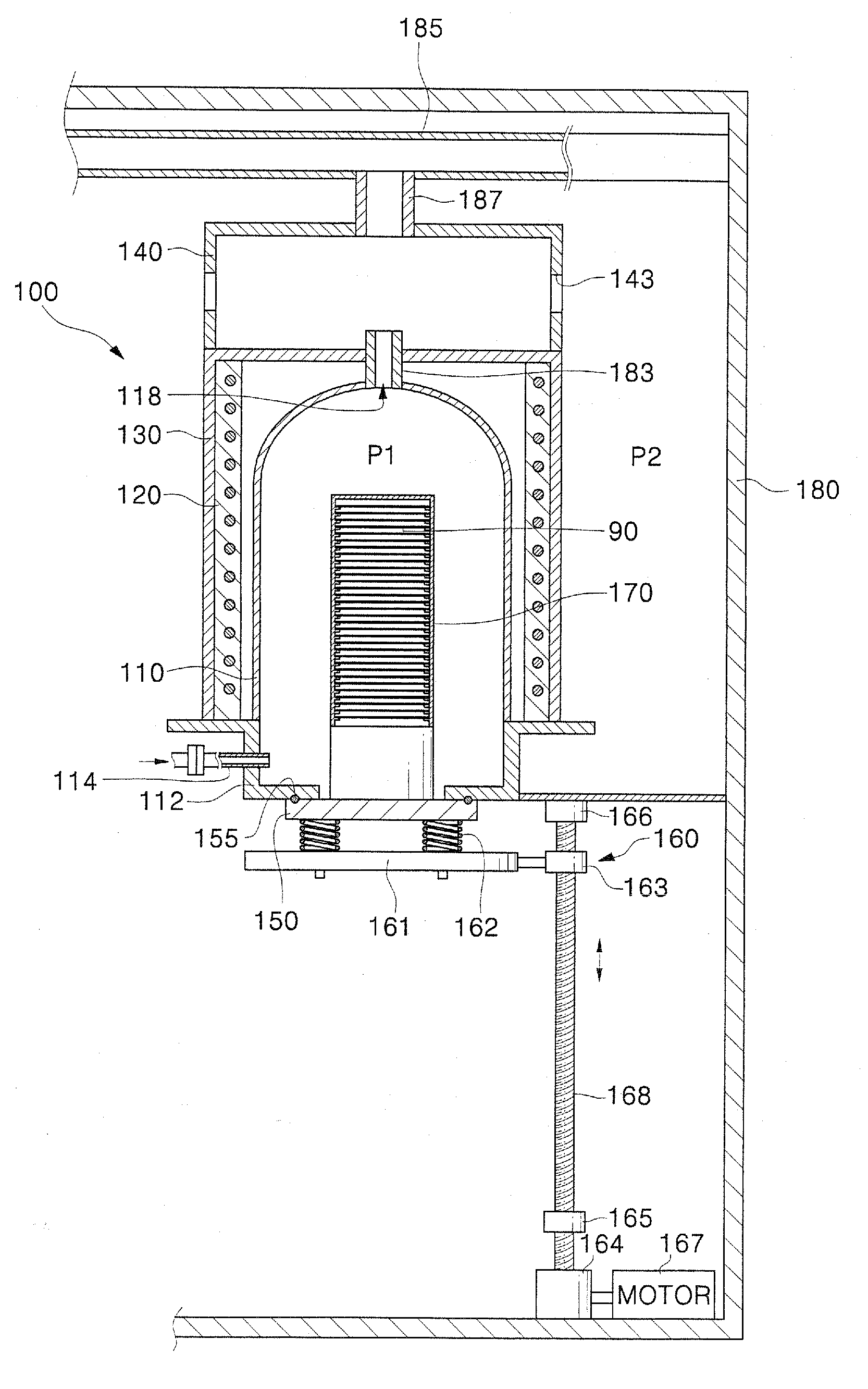
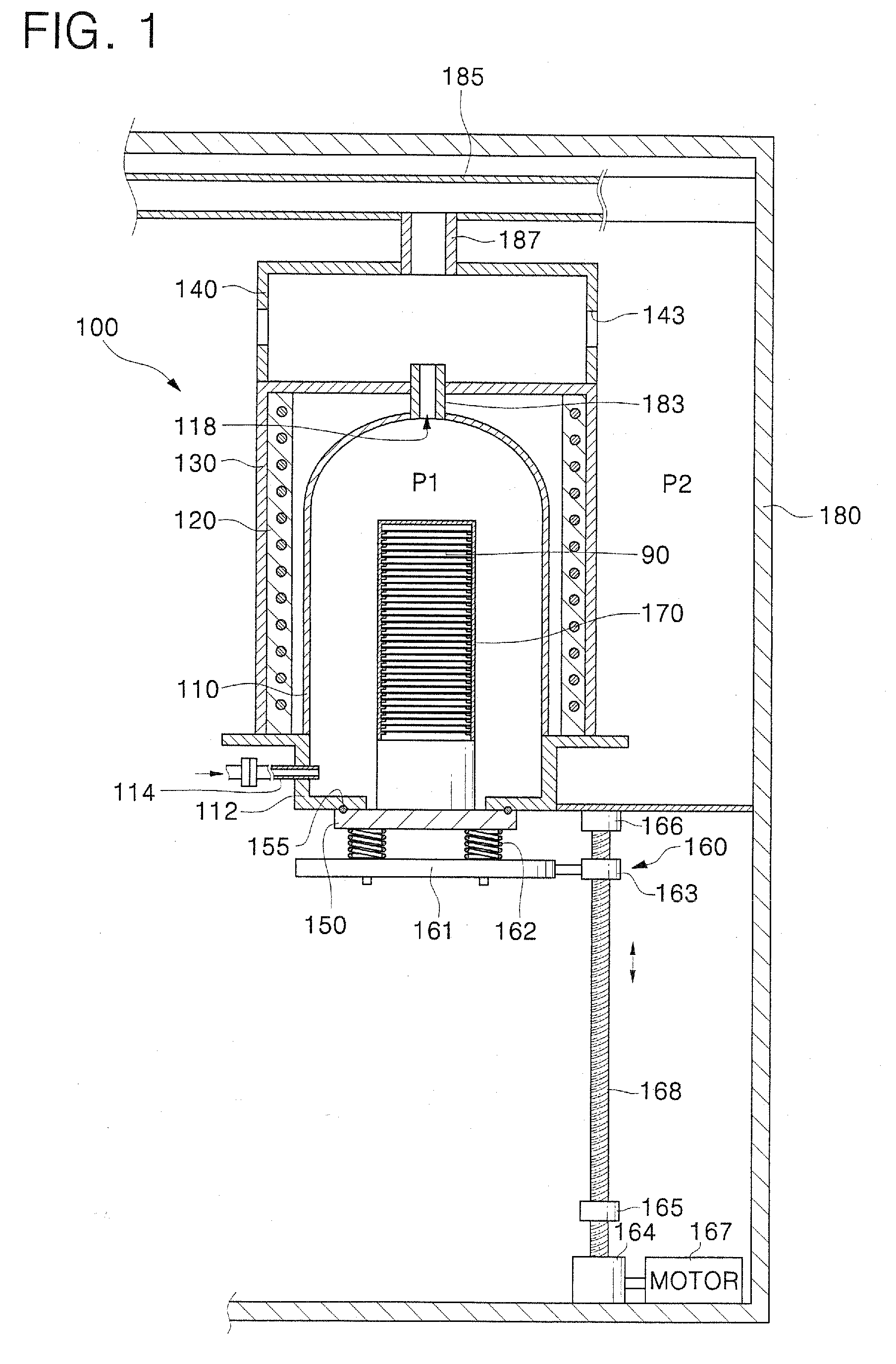
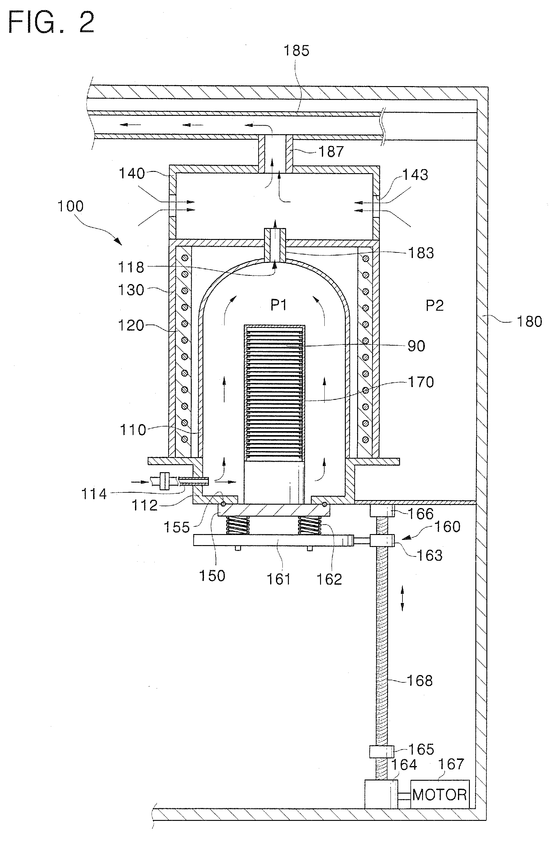
[0039]FIG. 1 is a cross-sectional view of heat treatment equipment 100 in accordance with an embodiment of the present invention, and FIG. 2 is a cross-sectional view illustrating a flow path of gases during exhaust of the heat treatment equipment 100 of FIG. 1.

[0040]As illustrated in FIGS. 1 and 2, the heat treatment equipment 100, comprising vertical furnace equipment with a vertical-type process tube 110, is installed inside a cl...


PUM

PropertyMeasurementUnit
shapeaaaaaaaaaa
pressureaaaaaaaaaa
movementaaaaaaaaaa

Abstract

In an embodiment, heat treatment equipment comprises a process tube, an exhaust duct connected to the process tube, and, during operation, exhausting gases present within the process tube. The heat treatment equipment also comprises a hollow pressure control member interposed between the process tube and the exhaust duct, the pressure control member being operatively connected to the process tube and the exhaust duct respectively, and including one or a number of openings. Negative pressure is avoided in the process tube during heat treatment processes so that unwanted gas and impurities cannot enter the process tube from outside.

Description

CROSS-REFERENCE TO RELATED APPLICATION[0001]This application claims priority from Korean Patent Application No. 2006-65611, filed Jul. 13, 2006, the disclosure of which is hereby incorporated herein by reference in its entirety as if set forth fully herein.BACKGROUND[0002]1. Technical Field[0003]The present invention relates to equipment used in a semiconductor device fabrication process, and more particularly, to heat treatment equipment for processing a substrate such as a wafer through a heat treatment process.[0004]2. Discussion of the Related Art[0005]Technology for semiconductor products continues to rapidly develop. Parameters of these semiconductor products, such as a processing speed and an amount of data stored per volume, have improved with the technology.[0006]Generally, semiconductor products are manufactured by the following processes: a wafer fabrication process of fabricating a wafer using pure silicon, a FAB process of fabricating semiconductor chips on the manufact...

Claims


Application Information

Patent Timeline
Patent Type & Authority Patents(United States)
IPC IPC(8): F27B5/00F27B5/10
CPCF27B17/0025H01L21/67109H01L21/67253H01L21/324
Inventor YANG, JAE-HYUNAHN, YO-HANLEE, KUN-HYUNGCHO, GUI-YOUNGJEONG, HONG-HEEKIM, MI-AE
Owner SAMSUNG ELECTRONICS CO LTD
Why Eureka
Try Eureka