Systems for MRI-guided cryosurgery

Active Publication Date: 2010-12-14
GALIL MEDICAL
View PDF20 Cites 23 Cited by
  • Summary
  • Abstract
  • Description
  • Claims
  • Application Information

AI Technical Summary

Problems solved by technology

Use of MRI in real time has major advantages for certain kinds of surgery, yet presents unique problems relating to the compatibility of equipment used within MRI's powerful magnetic environment.
Use of magnetic resonance imaging presents particular advantages for monitoring of cryosurgery procedures, yet existing systems for MRI-compatible cryosurgery have significant limitations and disadvantages.
It is a major limitation of existing imaging modalities that they are unable to display to a surgeon the border separating those first and second volumes.
If he underestimates the extent of the ablation volume, he destroys healthy tissue unnecessarily.
If he overestimates the extent of the ablation volume, he risks failing to destroy dangerous functional pathological (e.g. malignant) tissue structures.
Lack of systems providing accurate information on the size and position of an actual cryoablation volume is a major unsolved problem of contemporary cryoablation technique.
Currently known non-MRI imaging modalities are not adjusted nor designed to directly image the size and position of an actual cryoablation volume.
MRI imaging is capable of detecting and displaying tissue temperatures, yet no MRI system commercially available today is able to detect and display the borders of a cryoablation volume, because available MRI systems cannot detect and display temperatures within frozen tissue.
Although MRI detection of temperatures within very cold temperature ranges appears to be theoretically possible, no MRI system commercially available today provides this capability.
A plurality of synchronized ultrasound probes directed towards the iceball from various surrounding positions would provide better information, but such a solution has been found to be impractical in some cases and impossible in other cases.
Thus, both ultrasound and x-ray technologies deliver only partial information concerning the size and position and three-dimensional shape of the iceball, and neither can deliver direct information concerning the size and position and three-dimensional shape of the cryoablation volume contained within the iceball boundaries.
A surgeon who is unable to observe or accurately estimate the size and shape of an ablation volume is forced systematically underestimate the size of the ablation volume, at least when dealing with malignant or possibly malignant tumors, because total destruction of the entire tumor is essential to treatment, lest potentially lethal live cancer cells be left behind following surgery.
He thereby avoids uncertainty about whether all portions of a lesion (e.g., a malignant tumor) have been reliably destroyed, but unfortunately destroys considerable healthy tissue along with the lesion whose ablation is desired.
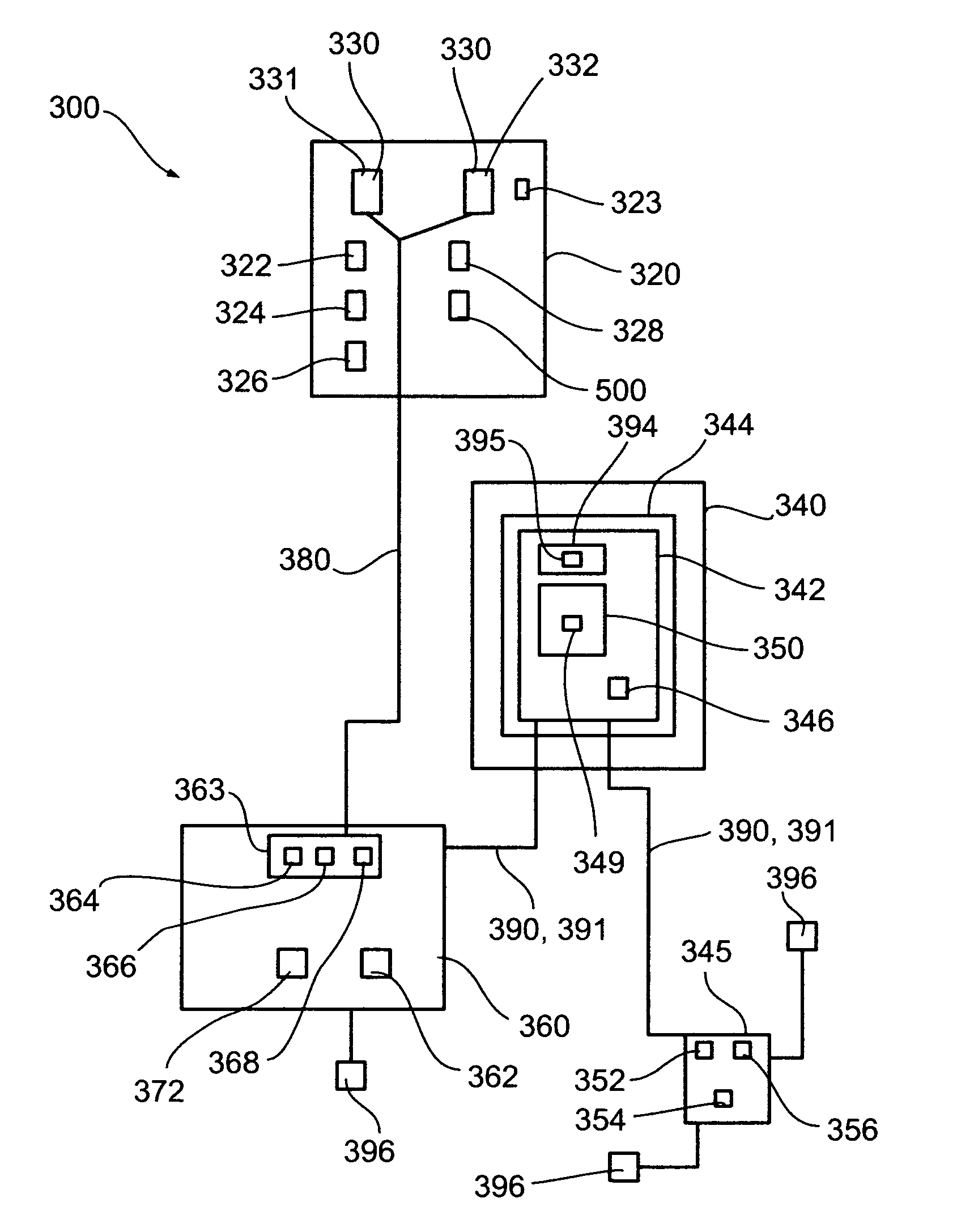
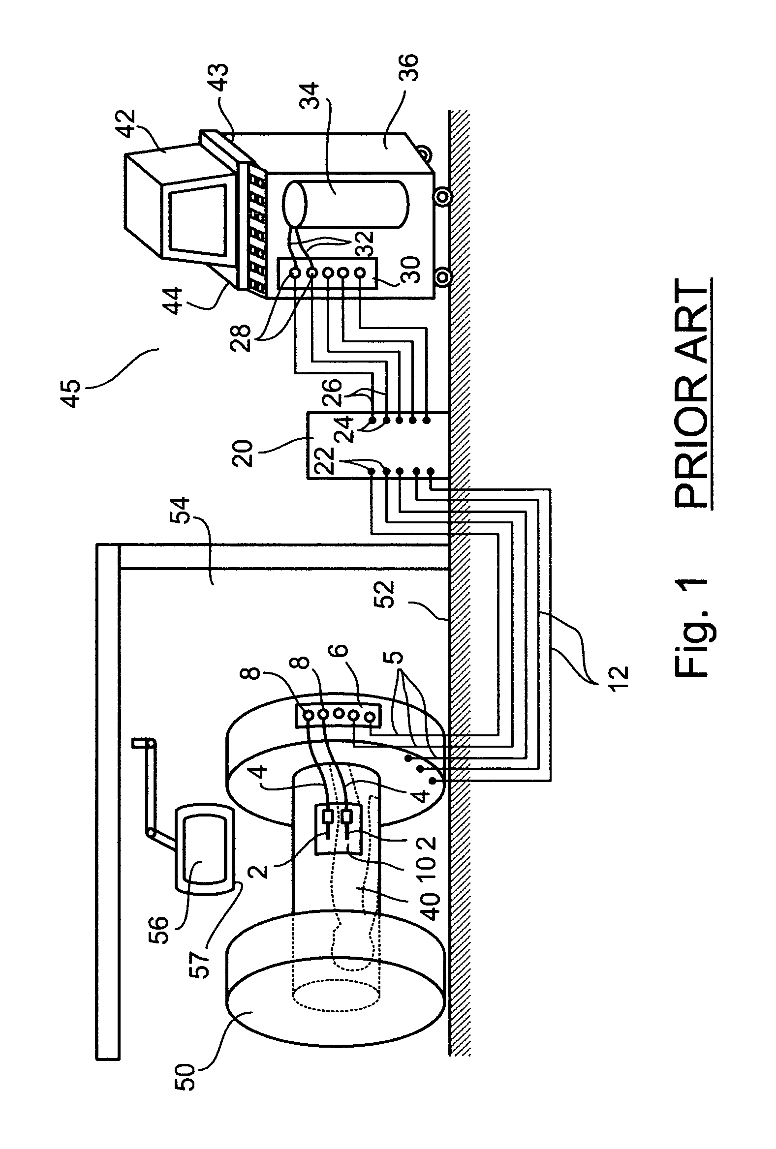
However, practice of cryosurgery under real-time MRI monitoring is difficult to accomplish.
A cryoprobe constructed of non-MRI-compatible materials may be subjected to powerful undesired forces generated by magnetic interaction between the probe and the MRI magnetic field, and / or may distort the magnetic field and thereby create distortion of the MRI image.
Induced currents can lead to uncontrolled phenomena such as distorted data and / or distorted control signals.
A major disadvantage of the configuration taught by Maytal is the described separation of control functions into inner and outer modules, which configuration provides user access to some control functions from within the inner module (e.g., control buttons selecting cooling or heating of cryoprobes), yet provides user access to other control functions from the outer module (e.g., manual control of gas valves, user interface for viewing a display reporting cryosurgery system status, etc.) In practice, systems conforming to the teachings of Maytal required two operators of the cryosurgical equipment, a first operator being a surge on, positioned within the magnetic field of the MRI equipment within an operating theatre environment, which first operator manipulates cryoprobes to perform the cryoablation, and a second operator who interacts with the user interface of the outer module, whose function includes inputting gas control commands and reporting orally to the surgeon, providing ongoing reports on cryosurgery system status which the surgeon, from his position near the patient, cannot see for himself and cannot directly control.
Maytal's system thus suffers from a serious disadvantage of inconvenience, in that it requires two operators, physically separated from one another, to operate the system, and in that the surgeon, in contact with a patient during the cryoablation does not have direct control over a variety of aspects of the cryoablation procedure.
Maytal's system is further disadvantageous in that the separation of functions into two modules as described does not allow for combined or coordinated presentation of both of cryosurgery status data and of MRI imaging data within a common display interface.
As stated above, currently available MRI systems do not provide direct information relating to size, position, and three-dimensional shape of the volume of total destruction (the ablation volume) created within an iceball during a cryoablation process.
Current MRI systems do not make recommendations to a surgeon during a cryoablation procedure, nor provide analyses specific to cryosurgical needs, nor do they automatically or partially automatically control the cryoablation procedure.

Method used


Image

  • Systems for MRI-guided cryosurgery
  • Systems for MRI-guided cryosurgery
  • Systems for MRI-guided cryosurgery

Examples


Embodiment Construction

[0068]The present invention is of systems and methods for MRI-guided cryosurgery. Specifically, the present invention enables a surgeon positioned next to a patient and within an MRI magnetic environment both to monitor progress of a cryosurgical intervention by observing MRI images of the intervention in real time, and to fully control aspects of operation of a cryosurgery apparatus by remotely controlling a fluid supply source positioned external to that magnetic environment, which fluid supply source supplies cryogenic fluids to cryoprobes operable within that magnetic environment, thereby enabling real-time MRI-guided control of a cryoablation process. A preferred embodiment enables calculation and display of borders of an ablation volume surrounding a cooled cryoprobe in real time, and further enables automatic control of elements of a cryoablation procedure, which elements are triggered when shape and position of that calculated ablation volume are found to bear a predefined r...


PUM


Abstract

The present invention is of systems and methods for MRI-guided cryosurgery. The systems enable a surgeon positioned next to a patient and within an MRI magnetic environment both to monitor progress of a cryosurgical intervention by observing MRI images of the intervention in real time, and to fully control aspects of operation of a cryosurgery apparatus by remotely controlling a fluid supply source positioned external to that magnetic environment, which fluid supply source supplies cryogenic fluids to cryoprobes operable within that magnetic environment, thereby enabling real-time MRI-guided control of a cryoablation process. A preferred embodiment enables calculation and display of borders of an ablation volume surrounding a cooled cryoprobe in real time, and further enables automatic control of elements of a cryoablation procedure, which elements are triggered when shape and position of that calculated ablation volume are found to bear a predefined relationship to the shape and position of a predefined treatment target.

Description

FIELD AND BACKGROUND OF THE INVENTION[0001]The present invention relates to devices, systems, and methods for MRI-guided cryosurgery. More particularly, the present invention relates to a cryosurgery apparatus compatible for use within the magnetic environment of a functioning magnetic resonance imaging system and fully controllable by a surgeon positioned within that magnetic environment, wherein the cryosurgery apparatus is also optionally operable under algorithmic control, control decisions being based on information gleaned from MRI monitoring of a cryosurgery procedure in real time.[0002]The present application relates to the use of cryosurgical tools in an MRI environment.[0003]In the early days of magnetic resonance imaging, MRI was used only as a diagnostic tool. MRI imaging was used to visualize body tissues and to locate and evaluate problematic tissue structures. When MRI-assisted diagnosis identified problems correctable by non-invasive surgery, non-MRI imaging modaliti...

Claims


Application Information

Patent Timeline
Patent Type & Authority Patents(United States)
IPC IPC(8): A61B18/02
CPCA61B18/02A61B2018/00005A61B2018/00577A61B2018/00791A61B2018/0287A61B2019/5236A61B2090/374
Inventor AMIR, URIBERZAK, NIRBLIWEIS, MORDECHAILEYBIN, YURAHILLELY, RON
Owner GALIL MEDICAL
Why Eureka
Try Eureka