Portable multi-function inspection systems and methods

a multi-functional, inspection system technology, applied in the field of inspection systems, can solve problems such as fraud or inadvertent failure to properly comply, levy of fines against the offending facility, and halt to ongoing production until the end of the year

Inactive Publication Date: 2010-12-14
TELEDYNE FLIR LLC
View PDF79 Cites 100 Cited by
  • Summary
  • Abstract
  • Description
  • Claims
  • Application Information

AI Technical Summary

Benefits of technology

[0010]More specifically in accordance with an embodiment of the present invention, an inspection system is disclosed to capture infrared images and to securely record date, time, and / or other relevant information along with the captured image. For example, the inspection system may securely record the information by employing a cryptographic hash function and a private key to sign the information and store for later verification. Alternatively or in addition, the infrared images may be encrypted using an encryption algorithm.

Problems solved by technology

Environmental and safety concerns may require periodic monitoring of production facilities or electrical devices and distribution systems, which may utilize toxic, flammable, controlled substances, or pose other types of hazards.
For example, failure to adequately document compliance with the requirements can result in a levy of fines against the offending facility and a halt to ongoing production until compliance can be verified.
With such a strong motivation to document compliance, there is also a possibility of fraud or inadvertent failures to properly comply.
Because it may be more expensive to acquire services from a certified inspector, there may be an attempt to utilize uncertified people.
In this case, the inspection may have been completed, but may have been accomplished by an uncertified or unqualified person.
There are also safety issues involved for an inspector when inspecting some types of electrical equipment or other types of production facilities.
For example, conventional types of inspection equipment may not provide sufficient information to the operator of the inspection equipment during an inspection procedure.

Method used


Image

  • Portable multi-function inspection systems and methods
  • Portable multi-function inspection systems and methods
  • Portable multi-function inspection systems and methods

Examples


Embodiment Construction

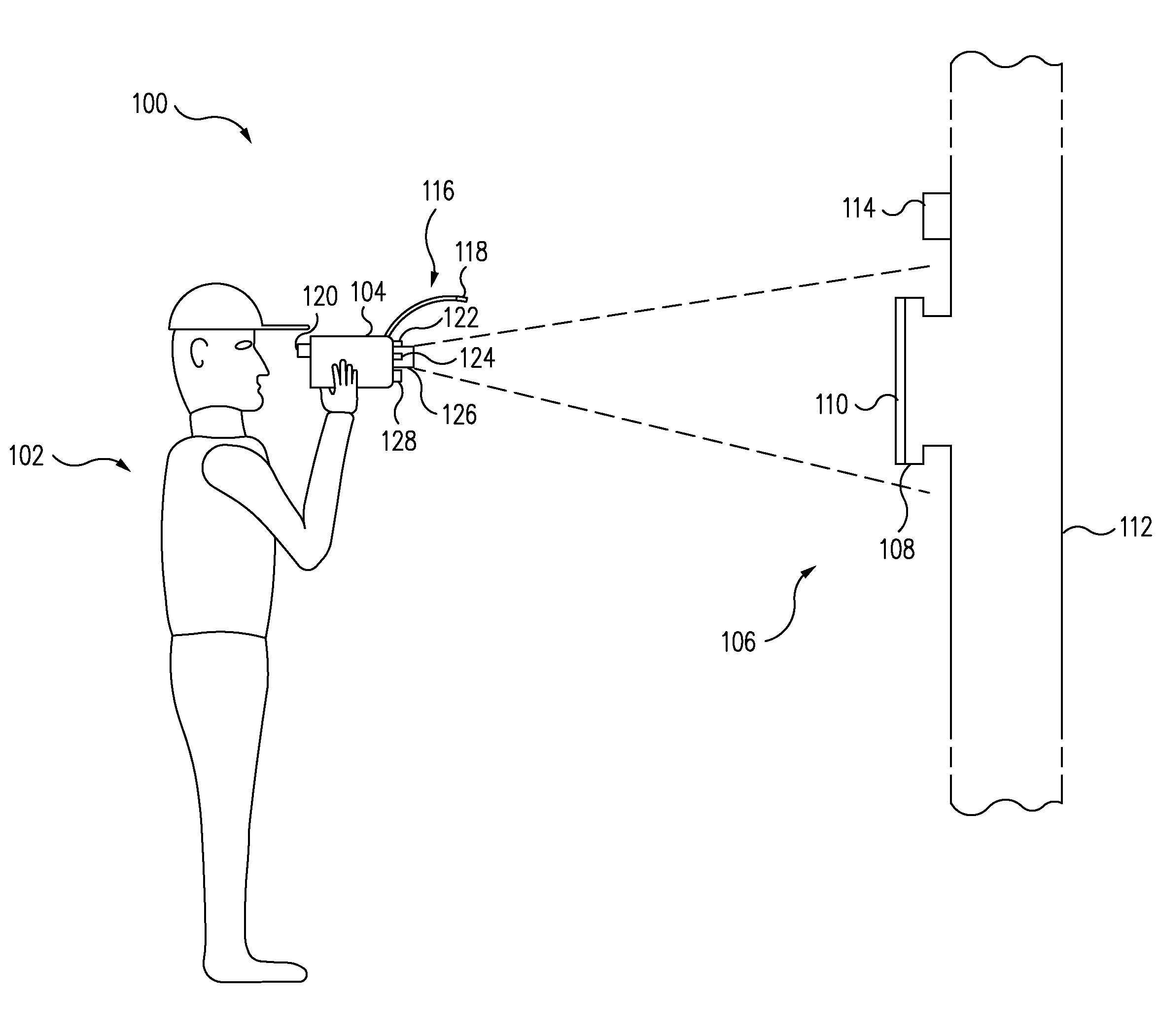
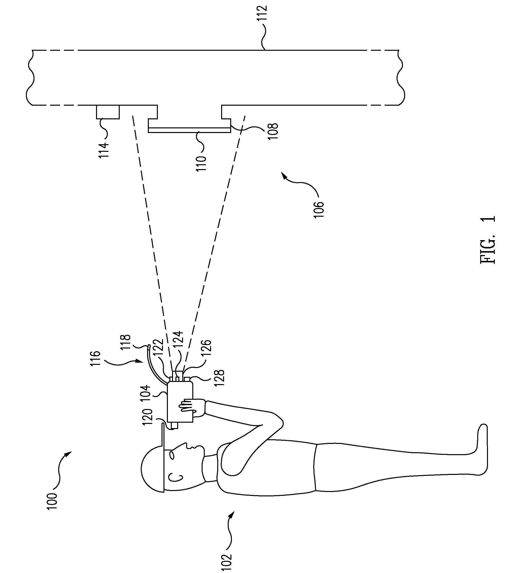
[0035]FIG. 1 shows an inspection station 100, in accordance with an embodiment of the present invention, where an inspector 102 is operating an inspection system 104 to examine (e.g., view on a display 120 an image received via a lens 126) an inspection target 106 (e.g., a pipe or container for a possible gas leak as shown or an electrical device for defects or temperature anomalies, as discussed further herein). As shown in FIG. 1 for this example, target 106 may be any component of a production facility, such as a juncture 108 between a cover plate 110 mounted on a pipe 112 that conducts a gas or gas-emitting substance.

[0036]In this example, plate 110 is intended to seal the juncture 108 by compressing a gasket (not shown) between plate 110 and pipe 112 so that a failure in the gasket might result in a gas leak that is detected by inspection system 104. Alternatively, any portion of any component at inspection station 110 may be inspected because any portion of the pipe 112 or ass...


PUM


Abstract

In accordance with at least one embodiment of the present invention, a portable inspection system is disclosed to capture inspection data, such as for example an infrared image, sound information, and / or electrical measurement information. The inspection data may be securely recorded (e.g., with an encryption algorithm) along with associated information, which may include for example date, time, system settings, operator identification, and location.

Description

REFERENCE TO PRIOR APPLICATION[0001]The present application is a continuation-in-part (CIP) of U.S. patent application Ser. No. 11 / 239,531 filed on Sep. 29, 2005 and a continuation-in-part (CIP) of U.S. patent application Ser. No. 11 / 403,534 filed on Apr. 12, 2006, which are incorporated herein by reference in their entirety.TECHNICAL FIELD[0002]The present invention relates generally to inspection systems, and more particularly, for example, to infrared inspection systems.RELATED ART[0003]Environmental and safety concerns may require periodic monitoring of production facilities or electrical devices and distribution systems, which may utilize toxic, flammable, controlled substances, or pose other types of hazards. For example in some production facilities, these substances pass through hundreds of pressurized pipes and tanks having thousands of seals, seams, and joints at various locations. As another example, an electrical distribution system may need to be monitored to detect pot...

Claims


Application Information

Patent Timeline
Patent Type & Authority Patents(United States)
IPC IPC(8): G01J5/00G01R31/308
CPCG01J5/02G01J5/025G01J5/026G01J5/0265G01J5/0275G01J5/08G01J5/089G01J5/0893G01J5/0896G01J5/042G01R31/308G01J5/07
Inventor SCANLON, TOMWOOLAWAY, JAMES T.MADDING, ROBERT P.
Owner TELEDYNE FLIR LLC
Why Eureka
Try Eureka