

Compact super wide-angle imaging system
a super wide-angle imaging and compact technology, applied in the field of wide-angle optical imaging systems, can solve the problems of long total track length, severe distortion of illumination, etc., and achieve the effect of short lens design
- Summary
- Abstract
- Description
- Claims
- Application Information
AI Technical Summary
Benefits of technology
Problems solved by technology
Method used
Image

Examples
example one
Family
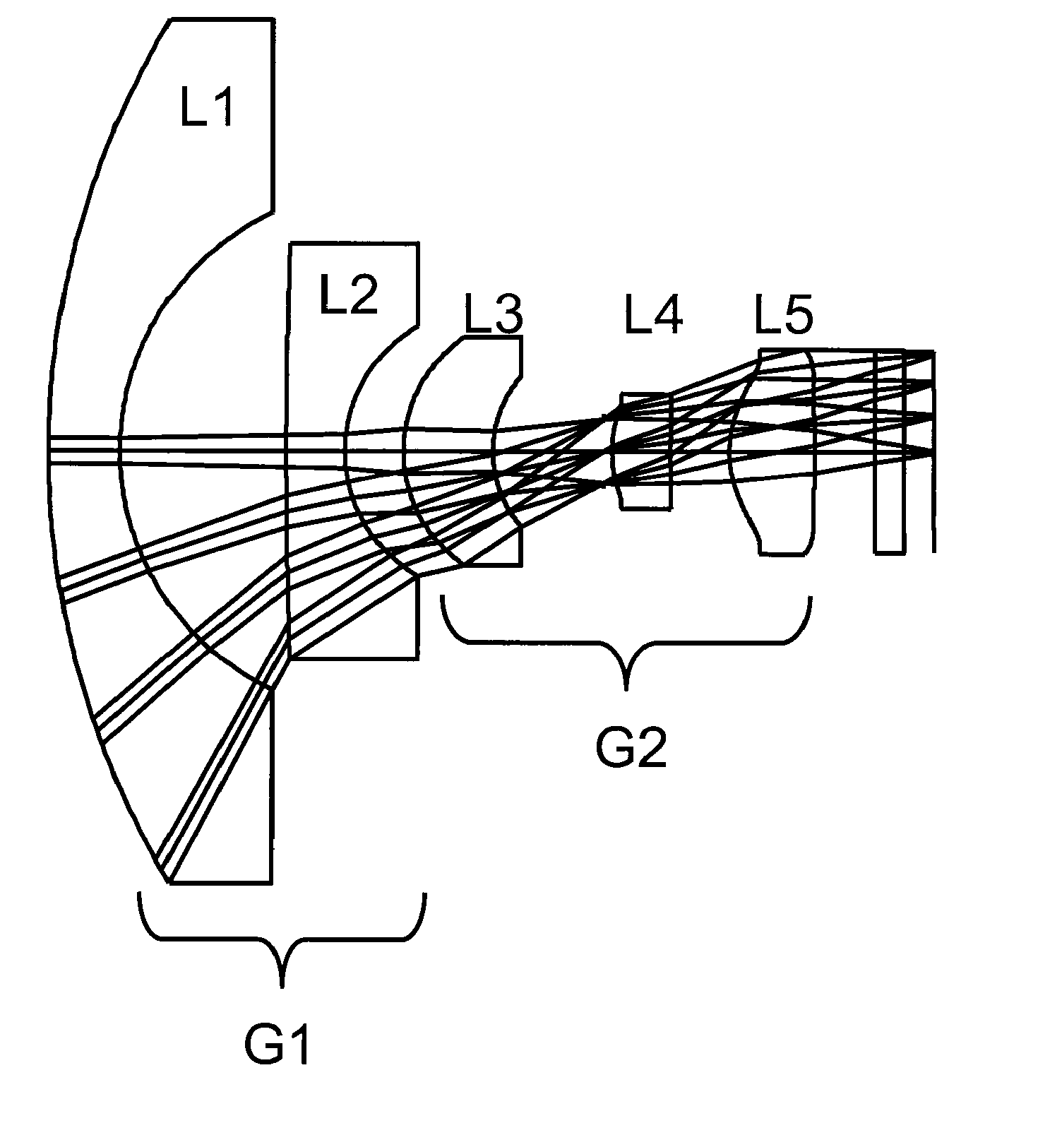
[0036]The optical system described in FIGS. 3-8 is but one of a family of designs based on similar principles. More generally, lens systems of this sort can be constructed from not more than five lenses without any cemented lens elements. The lens system has two lens groups. The first lens group (G1 in FIG. 3) is a negatively powered lens group. It bends the wide field angles into smaller field angles. The second lens group G2 is the positively powered lens group which acts to focus the light flux onto the photodetector array while balancing the optical aberrations. The second lens group also acts to reduce the lateral chromatic and distortion aberrations. The lens L5 closest to the image plane in the second lens group may have steep angles of incidence for the off-axis rays in order to counter the negative aberrations introduced by the first lens group having strong negative power.
[0037]In more detail, the first lens group G1 uses only two negatively powered lenses. The first...
example two
Family
[0070]The optical system described in FIGS. 9-13 is but one of a family of designs based on similar principles. More generally, lens systems of this sort can be constructed from not more than four lenses without any cemented lens elements. The lens system has two lens groups. The first lens group (G1 in FIG. 9) is a negatively powered lens group. It bends the wide field angles into smaller field angles. The second lens group G2 is the positively powered lens group which acts to focus the light flux onto the photodetector array while balancing the optical aberrations.
[0071]The first lens group G1 requires only two negatively powered lenses. The first lens L1 is a meniscus type lens having a convex surface facing the object. The second lens L2 is a negatively powered lens with a concave image-facing surface. The object-facing surface can be either concave or convex. The first lens L1 acts primarily to redirect the wide field angles towards the aperture stop. The second lens L2 i...
PUM
 Abstract
Description
Claims
Application Information