Heat sink assembly

a technology of heat sink and assembly, which is applied in the direction of lighting and heating apparatus, cooling/ventilation/heating modification, semiconductor devices, etc., can solve the problems of increasing the total weight of the electronic device where it is applied, and the manufacturing cost is relatively high, so as to improve the heat dissipation effect and reduce the weight. , the effect of low cos

Inactive Publication Date: 2010-12-14
ASIA VITAL COMPONENTS SHENZHEN CO LTD
View PDF9 Cites 3 Cited by
  • Summary
  • Abstract
  • Description
  • Claims
  • Application Information

AI Technical Summary

Benefits of technology

[0008]Accordingly, the present invention is directed to provide a heat sink assembly having improved heat dissipation effect at a low cost, which has a reduced weight and is easy to assemble.
[0009]A heat sink assembly of the present invention is characterized by comprising a base consisting of an aluminum casting and a copper base plate, a heat sink consisting of a plurality of aluminum heat fins, and at least a heat guide, wherein at least a groove is provided on each of the plurality of heat fins according to the quantity of said heat guide for passing the dissipation part of each said at least a heat guide, a cavity is opened on said aluminum casting for said copper base plate housing, and at least a trough is formed on the top surfaces of said copper base plate and said aluminum casting for placing the heat conduction part of each said at least a heat guide. Said copper base plate is placed against the heat source to transfer the heat through said base to said heat guide and then to said heat sink, so that the heat can be dissipated rapidly through said plurality of heat fins. In addition, the manufacturing cost and the total weight of the heat sink assembly are reduced.

Problems solved by technology

However, in such a conventional structure, the base (120) is made of copper material only and thus it is heavy in weight, which increases the total weight of the electronic device where it is applied.
In addition, the manufacturing cost is relatively high due to the high price of the copper.

Method used


Image

  • Heat sink assembly
  • Heat sink assembly
  • Heat sink assembly

Examples


Embodiment Construction

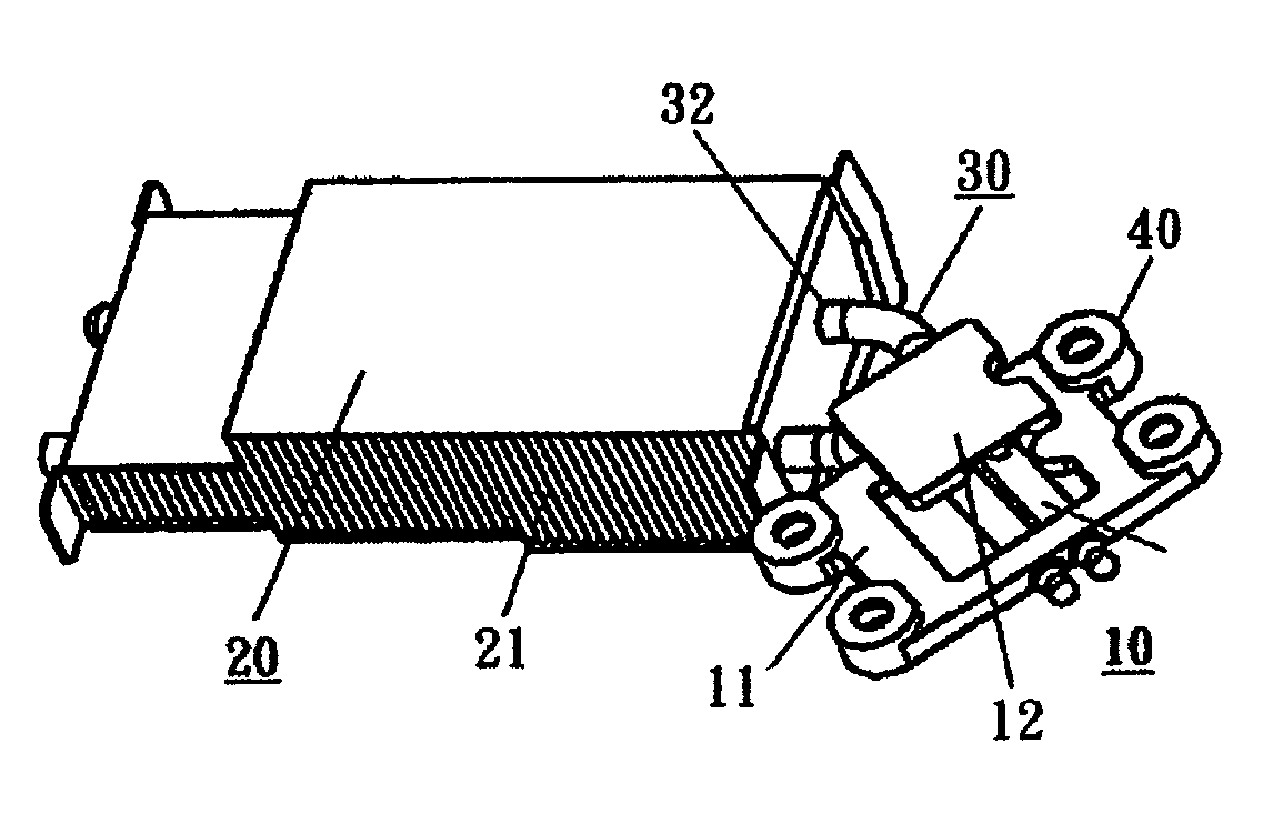
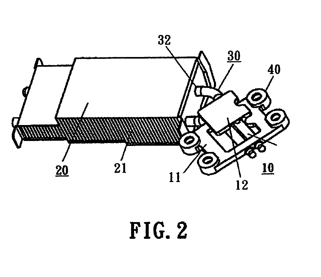
[0018]Referring to FIGS. 2, 3A, 3B and 4, the heat sink assembly of the present invention comprises a base (10) consisting of an aluminum casting (11) and a copper base plate (12), a heat sink (20) consisting of a plurality of heat fins (21), and at least a heat guide (30), wherein at least a through hole is provided at each of the heat fins (21) according to the quantity of said heat guide pipe (30) for the heat dissipation section (32) of each heat guide pipe (30) passing through, a hollow receiving space (13) is disposed in the middle of the aluminum casting (11) for fitting with the copper base plate (12), and at least an elongated recess (14) is disposed at the upper sides of said copper base plate (12) and said aluminum casting (11). The elongated recess(14) goes across the top sides of the copper base plate (12) and the aluminum casing (11), and extends to two opposite sides of aluminum casting (11) for placing the heat conduction part (31) the heat guide pipe (30), and said ...


PUM

PropertyMeasurementUnit
speedaaaaaaaaaa
weightaaaaaaaaaa
structureaaaaaaaaaa

Abstract

A heat sink assembly comprises a base consisting of an aluminum casting and a copper base plate, a heat sink consisting of heat fins, and at least a heat guide pipe; the heat guide pipe has a heat dissipation section passing through the heat fins; the aluminum casting has a hollow receiving space accommodating the copper base plate, and an elongated recess is disposed at the top sides of the copper base plate and the casting for placing the heat conduction part of the heat guide pipe; the copper base plate keeps contact the heat source and the heat transmits to the heat guide pipe and then is dissipated with the heat sink via the base rapidly. In addition, the weight of the heat sink assembly is decreased, and the manufacturing cost is reduced.

Description

BACKGROUND OF THE INVENTION[0001]1. Field of Invention[0002]The present invention relates to a heat sink assembly. More particularly, the present invention relates to a heat sink assembly comprising a heat base made of copper and aluminum, and further in coordination with the heat structure of a heat guide and a heat sink comprising a plurality of heat fins, which effectively achieves a best heat dissipation effect.[0003]2. Description of Related Art[0004]With the rapid development of the electronic science and technology industry, the electronic devices are required to operate at a higher speed. To ensure the normal operation of the electronic devices and prolong their life time, the heat dissipation treatment of the electronic device appears more and more important, and is highlighted for special attention. Therefore, various heat dissipation products corresponding to different application fields are developed to meet the demands of the market.[0005]FIG. 1 shows a conventional hea...

Claims


Application Information

Patent Timeline
Patent Type & Authority Patents(United States)
IPC IPC(8): H05K7/20F28F7/00
CPCH01L23/427H01L2924/0002H01L2924/00
Inventor YU, MING HAN
Owner ASIA VITAL COMPONENTS SHENZHEN CO LTD
Why Eureka
Try Eureka