Method and apparatus for designing backup communication path, and computer product

a communication path and backup technology, applied in the field of methods and apparatuses for designing backup communication paths, and computer products, can solve the problems of delay in communication path recovery, inability to realize fast service recovery, and increase in damage with the number of services

Inactive Publication Date: 2010-12-14
FUJITSU LTD
View PDF13 Cites 169 Cited by
  • Summary
  • Abstract
  • Description
  • Claims
  • Application Information

AI Technical Summary

Benefits of technology

[0024]It is an object of the present invention to solve at least the problems in the conventional technology.

Problems solved by technology

If there is failure in a large capacity WDM network, the damage increase with the number of services being provided by the system.
However, even if the communication path can be switched in parallel, if a longer time is taken until a communication node on the backup communication path receives a failure notification, fast service recovery cannot be realized.
Also in this case, the communication node 33 which switches the communication path is far away from the communication node 30 which has detected the failure and it takes much time to receive the failure notification message, which causes delay of the communication path recovery.
However, in the technique explained in Japanese Patent Application Laid-Open No. 2002-281068, it is possible to efficiently set a backup communication path which recovers communication within a required recovery time for a failure which occurs at one portion on a communication path, but there is a problem that the setting is difficult for a plurality of failure portions.
In other words, in the conventional technique, there is a problem that since the backup communication paths which can recover communication within a required recovery time are independently set, respectively, the communication resources are not shared between the set backup communication paths when a plurality of failure portions are assumed so that the backup communication path capable of efficiently utilizing the communication resources is difficult to set.

Method used


Image

  • Method and apparatus for designing backup communication path, and computer product
  • Method and apparatus for designing backup communication path, and computer product
  • Method and apparatus for designing backup communication path, and computer product

Examples


first embodiment

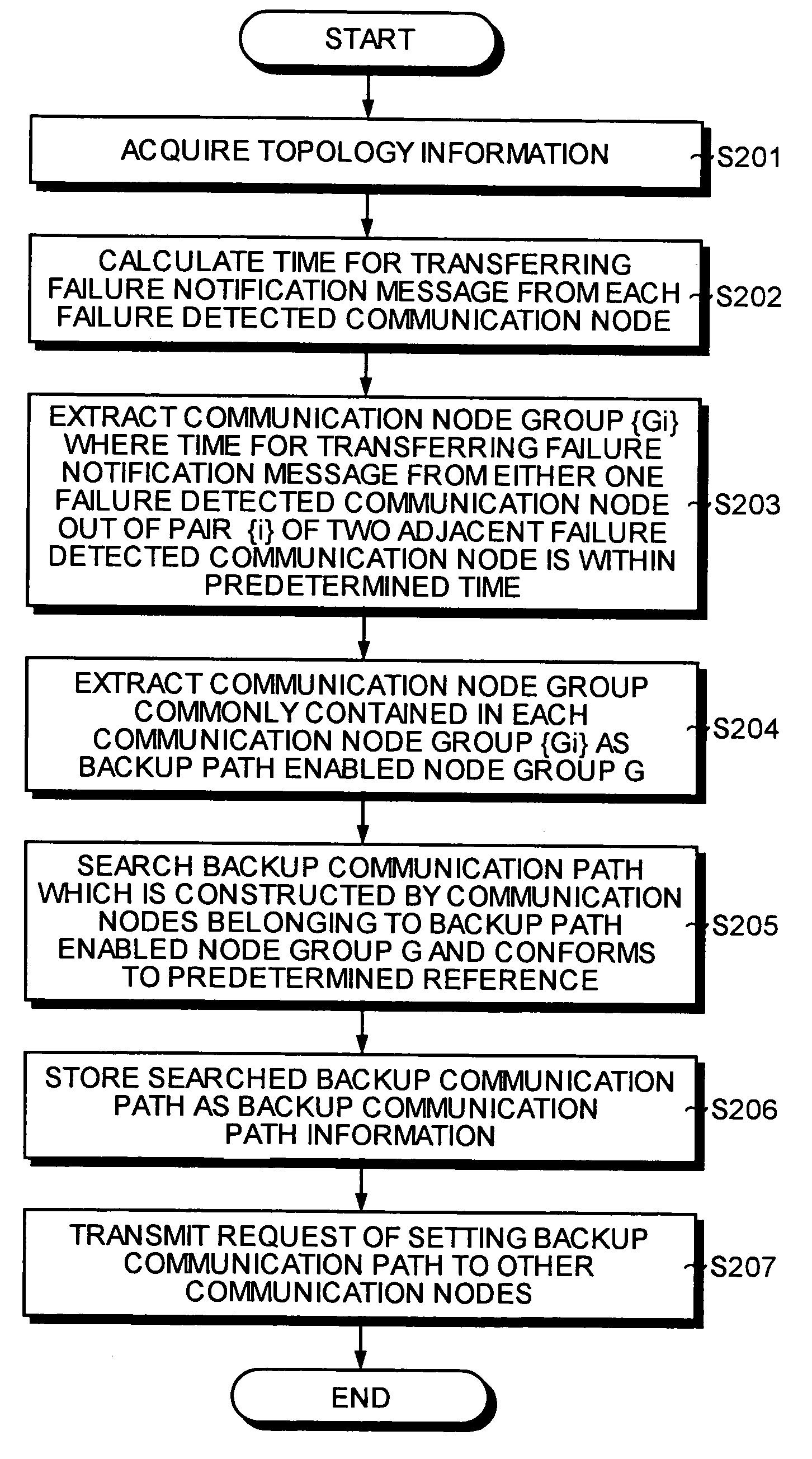
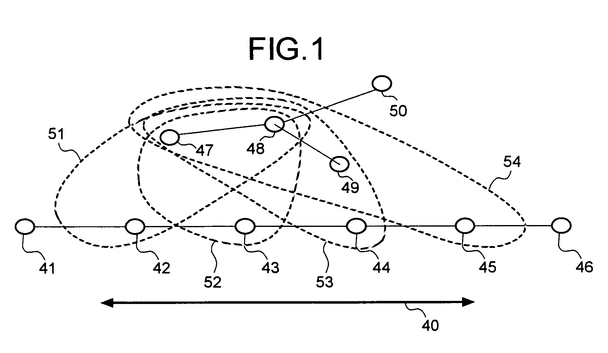
[0058]FIG. 1 is a schematic to explain a backup communication path design processing according to the present invention. As explained in FIG. 1, in the backup communication path design processing, communication nodes 47 and 48 where a time for transferring a failure notification message from a plurality of failure detected communication nodes 42, 43, 44, and 45 which detect a plurality of failures on an active communication path 40 to be protected is within a predetermined time are selected, and the selected communication nodes 47 and 48 are used to search for a backup communication path common to each failure which bypasses the failures.

[0059]The failure means a failure in a communication link or in a communication node. When a failure occurs in the communication link, a communication node connected to the communication link transmits a failure notification message.

[0060]When a failure occurs in the communication node, the communication node where the failure has occurred transmits...

second embodiment

[0115]In the present invention, there will be explained a case where when a failure is detected in any one of communication nodes across the failure in the bidirectional communication, a backup communication path which recovers the communication within a predetermined recovery time is designed.

[0116]First, a backup communication path design processing according to the second embodiment will be explained. FIG. 7 is a schematic to explain a failure notification area to which a failure notification message is transferred from two adjacent communication nodes, and FIG. 8 is a schematic to explain the backup communication path design processing according to the second embodiment.

[0117]As explained in FIG. 7, a communication node group where the time for transferring a failure notification message from one of communication nodes 81 and 83 on an active communication path 80 that detects a failure 82 is within a predetermined time is first extracted in the backup communication path design p...

third embodiment

[0142]In the present invention, there will be explained a case where a bypass communication node is searched for that selects a communication node on the active communication path where the time for transferring a failure notification message from a failure detected communication node is within a predetermined time and assumes the selected communication node as the start communication node.

[0143]First, a backup communication path design processing according to the third embodiment will be explained. FIG. 11 is a schematic to explain the backup communication path design processing where switching is performed by flooding a failure notification message.

[0144]As explained in FIG. 11, in the backup communication path design processing, a communication node 141 where the time for transferring a failure notification message by flooding from a plurality of failure detected communication nodes 142, 143, and 144 that detect the failures on an active communication path 140 to be protected is ...


PUM


Abstract

A communication node selecting unit selects a communication node where a time for transferring a failure notification message from a plurality of failure detected communication nodes which detect a plurality of failures on an active communication path to be protected is within a predetermined time, and a backup communication path designing unit searches, based on the selected communication nodes, for a common backup communication path which bypasses the failures.

Description

BACKGROUND OF THE INVENTION[0001]1) Field of the Invention[0002]The present invention relates to a technology for deciding a backup communication path in a communication network to take care of one or more failures in the link or the communication nodes.[0003]2) Description of the Related Art[0004]The communication traffics in the backbone networks is dramatically increasing along with upcoming of various new services and demands and wide spreading of the Internet. As a result, large capacity and high speed backbone networks are being designed based on the WDM (Wavelength Division Multiplexing) technique.[0005]The OXC (Optical Cross Connect) and the OADM (Optical Add-Drop Multiplexer) are being developed further for efficient operations by flexible control of mesh type network and sharing of preliminary wavelength, and construction of a new communication infrastructure and introduction of services are expected.[0006]If there is failure in a large capacity WDM network, the damage inc...

Claims


Application Information

Patent Timeline
Patent Type & Authority Patents(United States)
IPC IPC(8): H04J1/00H04L45/24H04L69/14H04J14/02H04L45/247H04L69/40
CPCH04J14/0227H04L45/00H04L45/22H04L45/28H04L45/62H04J14/0284
Inventor KANO, SHINYA
Owner FUJITSU LTD
Why Eureka
Try Eureka