Construction machine

a construction machine and construction technology, applied in the field of construction machines, can solve the problems of increasing casting costs and limit the improvement of the attachment strength of the handrail, and achieve the effects of improving the assembling property, improving the attachment strength of the floor plate, and convenient assembly

Inactive Publication Date: 2010-12-21
KOBELCO CONSTR MASCH CO LTD
View PDF12 Cites 9 Cited by
  • Summary
  • Abstract
  • Description
  • Claims
  • Application Information

AI Technical Summary

Benefits of technology

[0018]It is an object of the present invention to provide a construction machine capable of enhancing attachment strength of a handrail and strength of the handrail itself and also reducing casting cost in the case of a cast upper frame.

Problems solved by technology

Therefore, there is a limitation on improvement in attachment strength of the handrail 14.
Therefore, there is a problem that casting cost is increased.

Method used


Image

  • Construction machine
  • Construction machine
  • Construction machine

Examples


first embodiment

Refer to FIGS. 1 to 3

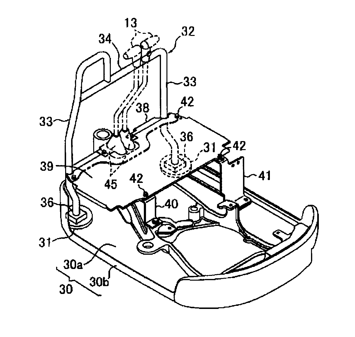
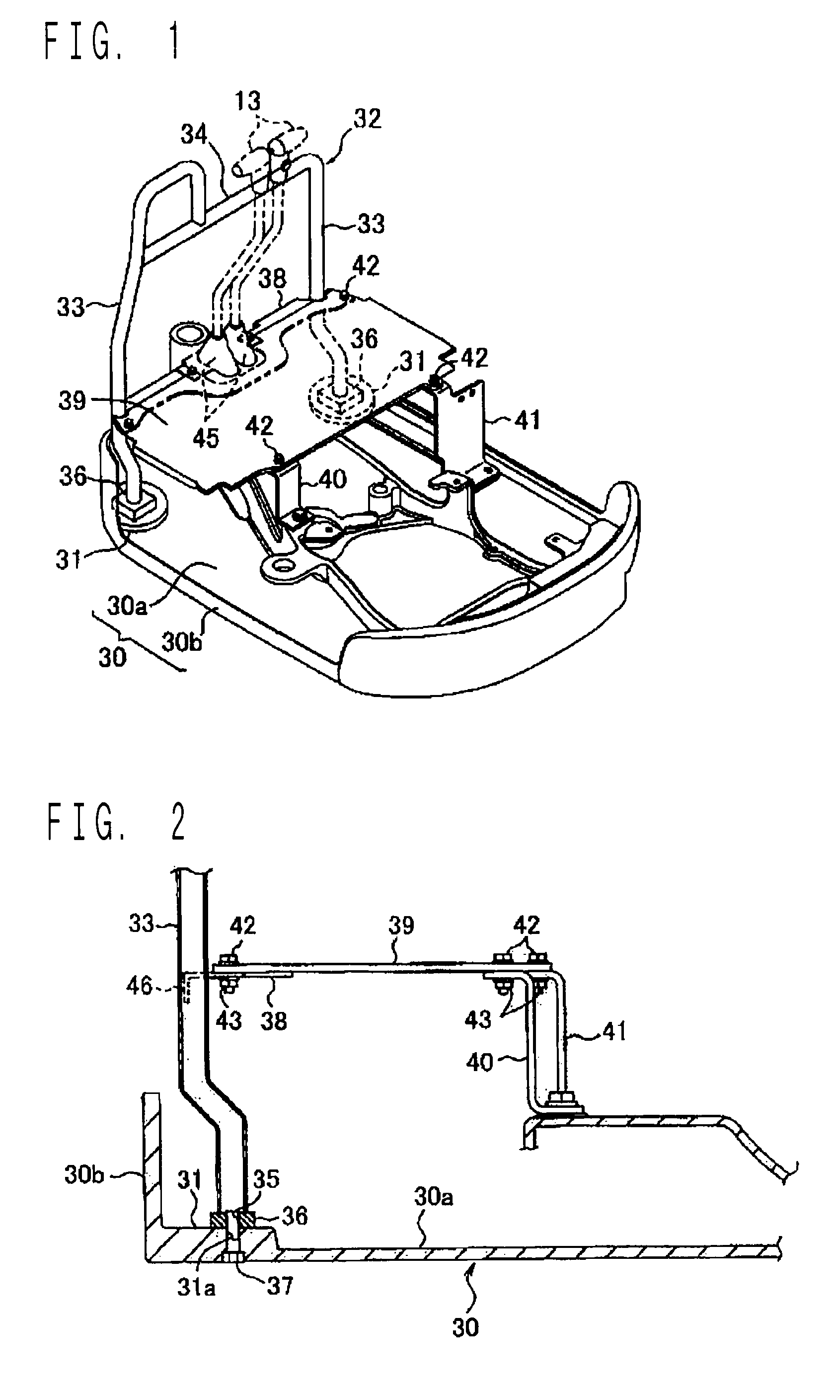
[0042]As shown in FIGS. 1 and 2, the upper frame 30 is formed into a shallow container provided with a standing edge portion 30b in a periphery thereof. Handrail mounts 31, 31 are provided on the left and right sides of a front end part of a bottom portion 30a.

[0043]The handrail mounts 31, 31 are only required to be slightly and partially bulged upward as a thick part. However, there is no need for protruding long in a columnar shape unlike a boss 19 in FIG. 9.

[0044]An attachment hole (not a screw hole but a simple through hole) 31a passing through in the up and down direction is provided in each of the handrail mounts 31, 31.

[0045]Meanwhile, a handrail 32 is formed by side supports 33, 33 and a lateral railing 34. Attachment plates 36, 36 are attached to lower ends of the side supports 33, 33.

[0046]A screw hole 35 (refer to FIG. 2) is provided in each of the attachment plates 36, 36. An attachment screw (bolt) 37 is screwed into the screw hole 35 in a state of...

second embodiment

Refer to FIGS. 4 to 6

[0059]A description will be only given to different points from the first embodiment.

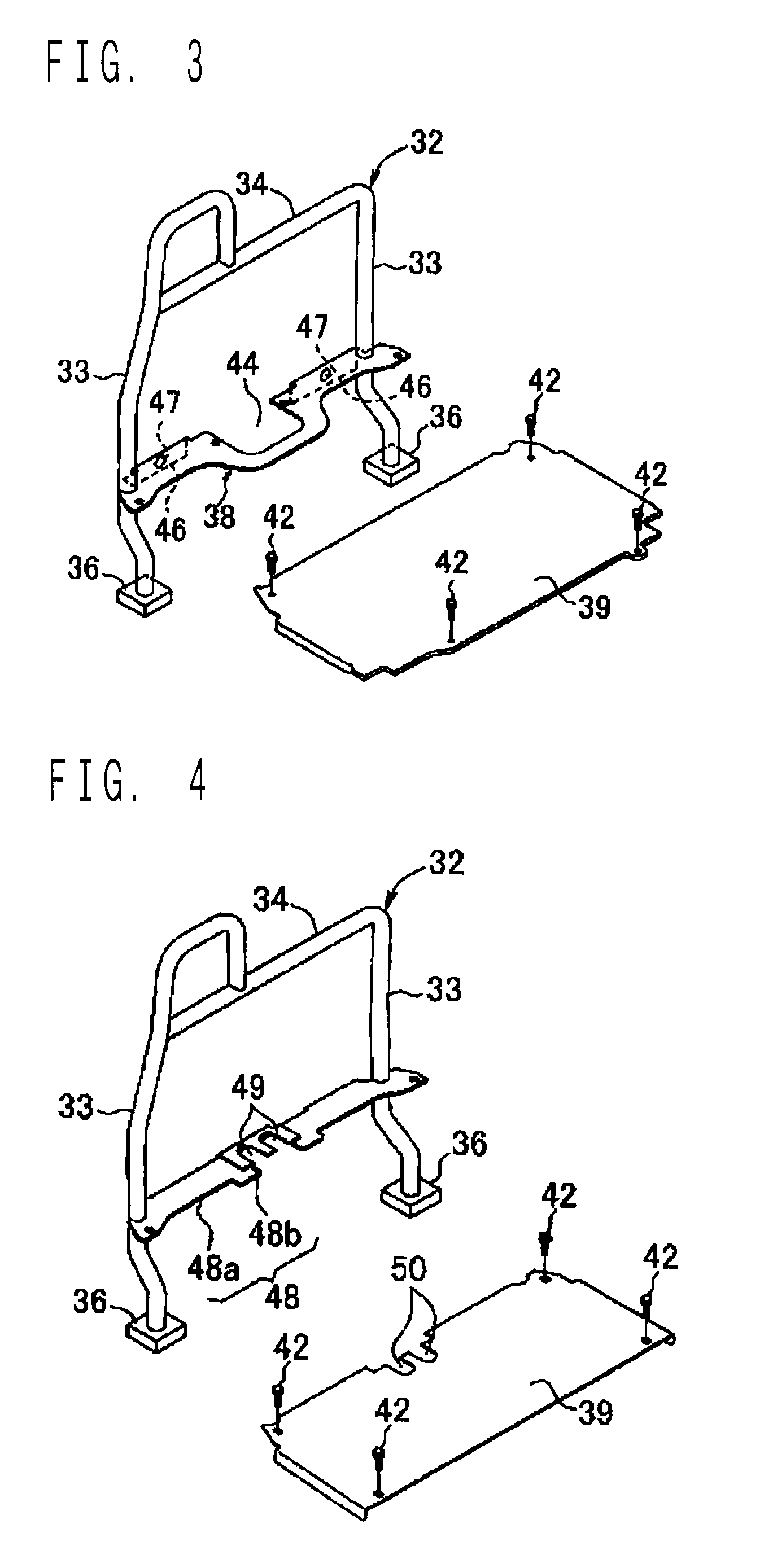
[0060]In a second embodiment, a pair of left and right notches 49, 49 is provided in a central part in the left and right direction of a base plate 48, and a pair of left and right notches 50, 50 is provided in a central part in the left and right direction of the floor plate 39. The former opens backward and the latter opens forward so as to face each other.

[0061]Lever through holes 51, 51 (refer to FIGS. 5 and 6) elongated in the front and back direction are formed by the above notches 49, 49 and 50, 50 in a state that the floor plate 39 is attached. Lower parts of a pair of the operation levers (only one lever is shown in FIG. 6) 13, 13 shown in FIG. 1 pass through the above lever through holes 51, 51 and are introduced to under the floor. Lower end parts of the boots 45 for covering an extra clearance of the lever through holes 51, 51 are engaged with and fixed to peripheral...


PUM


Abstract

Handrail mounts are provided in a bottom portion of a cast upper frame, and lower ends of side supports of a handrail are attached to the above handrail mounts. A base plate for attaching a floor plate is hanged and fixed between the side supports at a higher position than the attachment position, and a front end part of the floor plate is attached to the above base plate.

Description

BACKGROUND OF THE INVENTION[0001]1. Field of the Invention[0002]The present invention relates to a construction machine in which a handrail is attached to an upper rotating body such as a small-sized hydraulic excavator.[0003]2. Description of the Related Art[0004]A description will be given to the related art taking a small-sized hydraulic excavator (referred to as a mini excavator) serving as a preferred example of the present invention as an example.[0005]The above excavator is provided with an upper rotating body 2 disposed on a crawler type lower traveling body 1 rotatably around a vertical axis, and a working attachment 3 installed in a front end part of the above upper rotating body 2 as shown in FIG. 7.[0006]The working attachment 3 is provided with a raising and lowering boom 4. An arm 5 is attached to a front end of the above boom 4, and a bucket 6 is attached to a front end of the above arm 5. The reference numeral 7 denotes a boom raising and lowering cylinder for raisin...

Claims


Application Information

Patent Timeline
Patent Type & Authority Patents(United States)
IPC IPC(8): B60J7/00
CPCE02F3/325E02F9/0833E02F9/16
Inventor FUJII, TOKUOMIYACHI, ISAOKOBAYASHI, KAZUAKI
Owner KOBELCO CONSTR MASCH CO LTD
Why Eureka
Try Eureka