Centrifugal compressor and dry gas seal system for use in it

a centrifugal compressor and dry gas seal technology, which is applied in the direction of machines/engines, mechanical equipment, liquid fuel engines, etc., can solve the problems of dry gas seal breaking, deterioration of seal means, and limited time for checking valves, so as to avoid unnecessary stop of centrifugal compressor operation and prevent deterioration of seals

Inactive Publication Date: 2010-12-21
HITACHI LTD
View PDF11 Cites 39 Cited by
  • Summary
  • Abstract
  • Description
  • Claims
  • Application Information

AI Technical Summary

Benefits of technology

[0009]To solve such failures, the method disclosed in JP-A-9-60734 for collecting the leak gas by installing the leak gas tank on the downstream side of the check valve can prevent influences on the downstream side from reaching the seal means. However, a new facility for processing the collected leak gas is required, so that an apparatus including auxiliary machines is enlarged and costs are increased.
[0010]The present invention is made in view of the above-mentioned failures of the prior arts, and an object of the present invention is to protect seal means in dry gas sealing. Another object of the present invention is to avoid an unnecessary stop of operation of a centrifugal compressor.
[0011]In an aspect of the present invention for achieving the above-mentioned objects, a multistage centrifugal compressor has primary dry gas seal means for preventing leakage of working gas from a machine inner side, and secondary dry gas seal means for backing up the first dry gas seal means. A seal gas line for introducing the gas leaked from the first and second dry gas seal means to the outside of the machine is installed between the primary dry gas seal means and the secondary dry gas seal means, and has an orifice and a check valve. Buffer means is installed between the orifice and the check valve.
[0015]According to the present invention, the buffer means capable of absorbing influences on the downstream side is installed to a primary dry seal line for introducing the leak gas from the seal means, so that influences on the seal means by the influences on the downstream side can be reduced and the seal means can be protected. Also, the improper actuation of the flow meter installed on the upstream side of the orifice and detecting deterioration of the seal means can be prevented, and an unnecessary stop of operation of the centrifugal compressor can be avoided.

Problems solved by technology

The check valve requires a limited time till closure, and cannot cope with a rapid pressure increase.
As a result, abnormal pressure generated on the downstream side of the dry gas seal is propagated to the dry gas seal, and a back flow is generated inside the dry gas seal, so that the dry gas seal might be broken.
Also, the back flow generated by the generated pressure increase improper actuates a flow meter monitoring deterioration of a performance of the dry gas seal, and causes a frequent action of alarm / shut-down, so that a life of a centrifugal compressor might be reduced.
However, a new facility for processing the collected leak gas is required, so that an apparatus including auxiliary machines is enlarged and costs are increased.

Method used


Image

  • Centrifugal compressor and dry gas seal system for use in it
  • Centrifugal compressor and dry gas seal system for use in it
  • Centrifugal compressor and dry gas seal system for use in it

Examples


Embodiment Construction

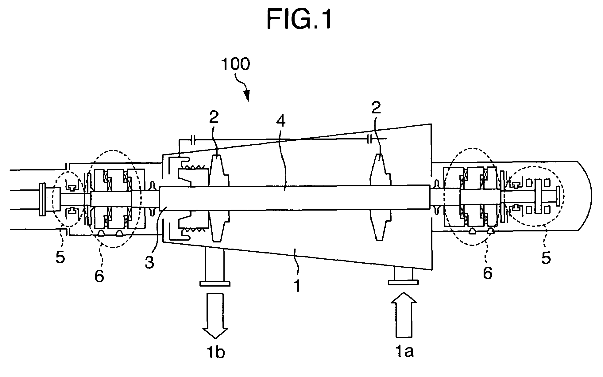
[0019]Now, one embodiment of a multistage centrifugal compressor according to the present invention and a dry seal system used for it will be explained. FIG. 1 diagrammatically shows a multistage centrifugal compressor 100. In a uniaxial multistage centrifugal compressor handling process gas such as ethylene gas, a plurality of centrifugal impellers 2 are mounted to a rotary shaft 3. A rotor 4 is formed integrally by the rotary shaft 3 and the centrifugal impellers 2. The rotor 4 is supported radially and axially by bearings 5 installed on both of axial ends of the rotary shaft 3. The rotor 4 and the bearings 5 are housed in a casing 1. The bearings 5 comprise journal bearings rotatably supporting the rotary shaft 3 in the radial direction, and a thrust bearing restraining the axial movement of the rotary shaft 3. In FIG. 1, the journal bearing is installed on a left axial end, and the thrust bearing and the journal bearing are installed on a right axial end.

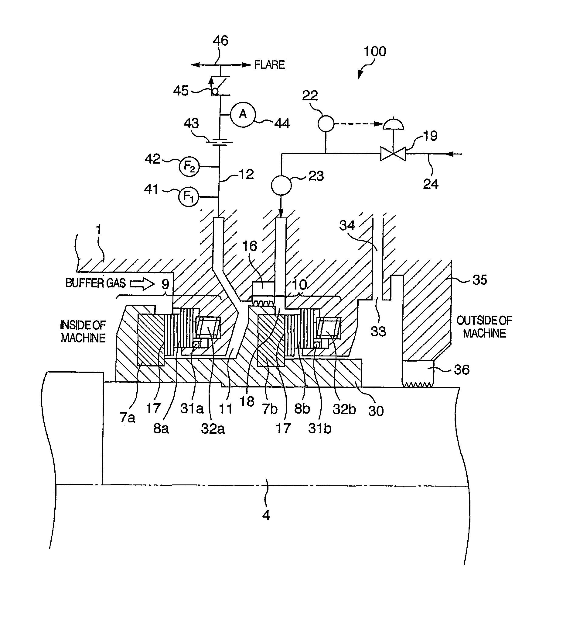
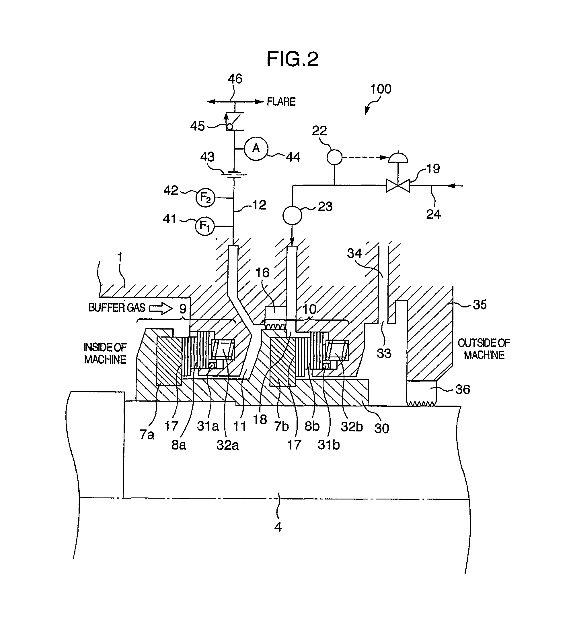
[0020]Seal means 6 are i...


PUM


Abstract

The present invention relates to a centrifugal compressor using a dry gas seal system for protecting seal means. A multistage centrifugal compressor has primary dry gas seal means for preventing leakage of working gas from a machine inner side, and secondary dry gas seal means for backing up the first dry gas seal means. A seal gas line for introducing the gas leaked from the first and second dry gas seal means to the outside of the machine is installed between the primary dry gas seal means and the secondary dry gas seal means. The gas seal line has an orifice and a check valve, and buffer means is installed between the orifice and the check valve.

Description

BACKGROUND OF THE INVENTION[0001](1) Field of the Invention[0002]The present invention relates to a centrifugal compressor, and in particular to a dry gas seal system thereof.[0003](2) Description of Related Art[0004]Examples of conventional dry gas seal systems for use in a centrifugal compressor are disclosed in JP-A-9-60734, WO 01 / 007791 A1, and JP-A-11-182690. In the dry gas seal system disclosed in JP-A-9-60734, to collect process gas leaked from a temporary seal of a dry gas seal for preventing environmental contamination, and to save resources, a small-sized compressor is installed to a leak gas line of the process gas leaked from the temporary seal of the dry gas seal. Furthermore, a cushion tank keeping a pressure balance is installed on a suction side of the small-sized compressor. The process gas whose pressure is increased is returned to a process gas line by the small-sized compressor.[0005]The dry gas seal system disclosed in WO 01 / 007791 A1 is equipped with a primary ...

Claims


Application Information

Patent Timeline
Patent Type & Authority Patents(United States)
IPC IPC(8): F01D11/06F04D29/08
CPCF01D11/04F04D29/124
Inventor ITO, TOSHIOYAMADA, HIROSHI
Owner HITACHI LTD
Why Eureka
Try Eureka