
Trocar assembly with pneumatic sealing

a trocar and pneumatic sealing technology, applied in the field of surgical devices, can solve the problems of inability to fully seal the trocar, inhibit the free movement of surgical instruments and/or removal, and also the seal is vulnerable to damag

Inactive Publication Date: 2010-12-21
SURGIQUEST
View PDF62 Cites 183 Cited by
  • Summary
  • Abstract
  • Description
  • Claims
  • Application Information

AI Technical Summary

Benefits of technology

The present invention provides a trocar for use in minimally invasive surgical procedures that creates a fluid seal around an instrument to prevent leakage. The trocar includes an elongated body with nozzle means for delivering a pressurized flow of fluid to the nozzle means. The nozzle means is directed at an angle of up to 90 degrees to create a pressure gradient within the body. The fluid seal is created without the need for mechanical valves, minimizing friction and allowing for safer and more accurate procedures. The nozzle means can be directed at an angle of up to 75 degrees. The trocar can also include a recirculation chamber for collecting and treating fluid. The technical effects of the invention include improved sealing capabilities, reduced friction, and improved safety and efficiency in minimally invasive surgeries.

Problems solved by technology

However, sealing in this manner is not usually complete, such seals cannot seal between multiple instruments, and such seals also inhibit free movement of the surgical instruments and / or removal of tissue through the trocar.
Such seals are also vulnerable to damage during the surgical procedure.
However, these types of mechanical valves suffer from similar drawbacks.
Most valves, and particularly duckbill-type valves, which include resilient valve members that directly contact surgical instruments, not only interfere with the movement of surgical instruments, but reduce the ability of a surgeon to accurately sense the patient anatomy on which the surgeon is operating.

Method used


Image

  • Trocar assembly with pneumatic sealing
  • Trocar assembly with pneumatic sealing
  • Trocar assembly with pneumatic sealing

Examples


Embodiment Construction

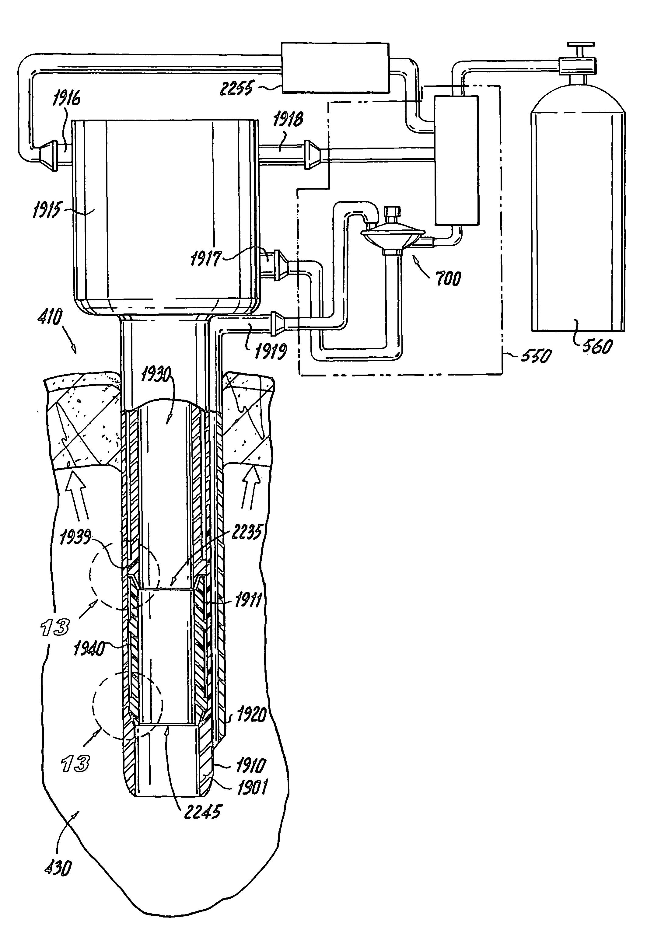
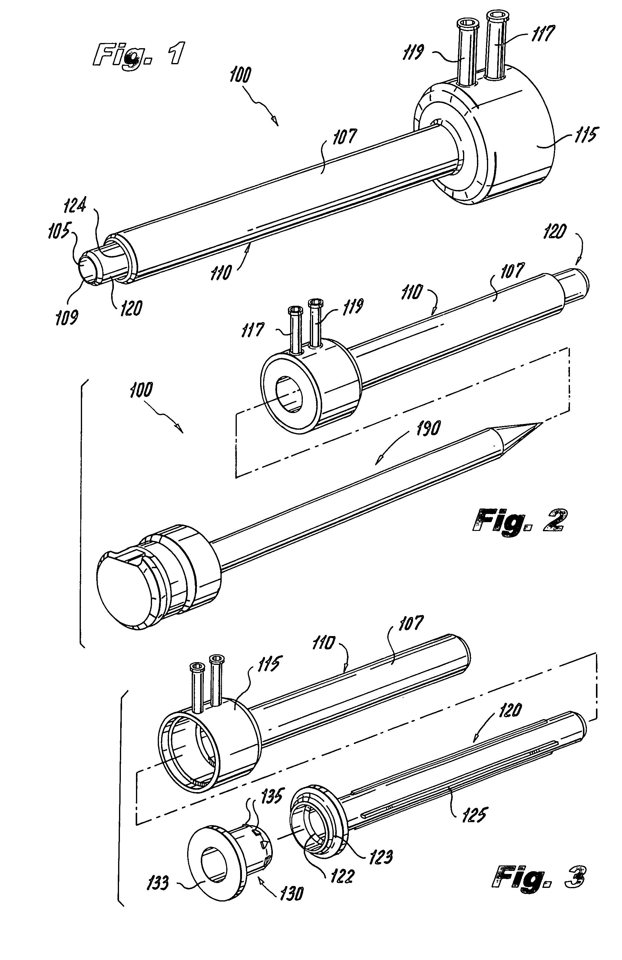
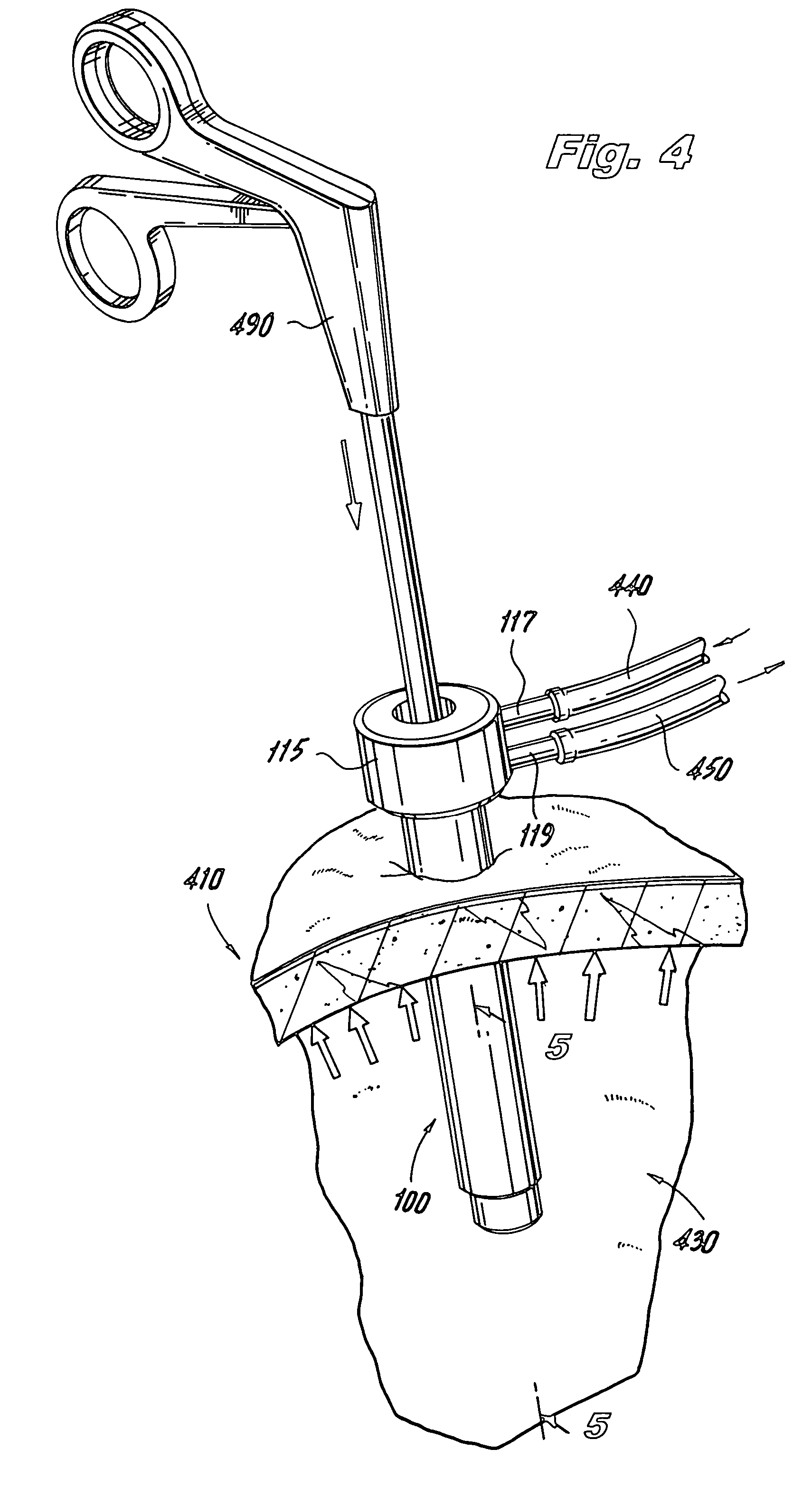
[0088]Referring now to the drawings, wherein like reference numerals identify similar structural aspects of the subject trocars and systems therefor, an exemplary embodiment of the pneumatically sealable trocar in accordance with the invention is shown in FIGS. 1-6, and is designated generally by reference character 100. Other embodiments of pneumatically sealable trocars in accordance with the invention, or aspects thereof, are provided in subsequent figures, which are described in detail below.

[0089]With reference to FIGS. 5 and 6a, the trocar 100 includes an elongated body having an outer tubular member 110, and a coaxial inner tubular member 120. The inner tubular member 120 includes an inner surface 105 surrounding a lumen or channel 106, through which an instrument (e.g., instrument 490) can be inserted into a cavity, such as abdominal cavity 430 of a patient. Spiral or helical grooves can be provided in the surface 105 of the trocar to impart a rotation to fluid either enteri...


PUM


Abstract

A trocar for use in a minimally invasive surgical procedure includes an elongated body, nozzle means and means for delivering a pressurized flow of fluid to the nozzle means. The elongated body has a generally tubular configuration with coaxially arranged inner and outer walls and longitudinally opposed proximal and distal end portions, with the inner wall defining a lumen to accommodate passage of an instrument therethrough. The nozzle means is operatively associated with the inner wall of the body for directing pressurized fluid into the lumen to develop a pressure differential in an area within a region extending from a location adjacent a distal end portion of the lumen to a location adjacent a proximal end portion of the lumen, to form a fluid seal around an instrument passing therethrough.

Description

CROSS-REFERENCE TO RELATED APPLICATIONS[0001]This application is a continuation-in-part of U.S. patent application Ser. No. 10 / 776,923, filed Feb. 11, 2004, now U.S. Pat. No. 7,338,473, which is a continuation-in-part of U.S. patent application Ser. No. 10 / 739,872, filed Dec. 18, 2003, now U.S. Pat. No. 7,285,112, which is a continuation-in-part of U.S. patent application Ser. No. 10 / 441,149, now U.S Pat. No. 7,182,752, filed May 17, 2003. Each of the foregoing applications also claims priority to U.S. Provisional Application Ser. No. 60 / 461,149, filed Apr. 8, 2003. Each of the foregoing applications is expressly incorporated herein by reference.BACKGROUND OF THE INVENTION[0002]1. Field of the Invention[0003]The present invention relates to surgical devices for providing access into a body cavity of a patient during a surgical procedure, and more particularly, to a pneumatically sealed trocar assembly.[0004]2. Description of the Related Art[0005]Laparoscopic, or “minimally invasive”...

Claims


Application Information

Patent Timeline
Patent Type & Authority Patents(United States)
IPC IPC(8): A61M5/178A61B17/00A61B17/34A61B19/00
CPCA61B17/3421A61B17/3423A61B17/3462A61B17/3474A61B17/3498A61M13/003A61B2017/00265A61B2019/464A61M2202/0225A61M2205/3344A61B2090/064A61M1/28A61M13/006
Inventor STEARNS, RALPHSTUBBS, JACK B.
Owner SURGIQUEST
Learn More