
Fuel system with improved fuel cell shutdown

a fuel cell and shutdown technology, applied in the field of fuel cells, can solve the problems of fuel cell degradation and use of stored nitrogen or helium, and achieve the effect of increasing electric load and decreasing airflow

Inactive Publication Date: 2010-12-21
TOYOTA MOTOR CO LTD
View PDF21 Cites 1 Cited by
  • Summary
  • Abstract
  • Description
  • Claims
  • Application Information

AI Technical Summary

Benefits of technology

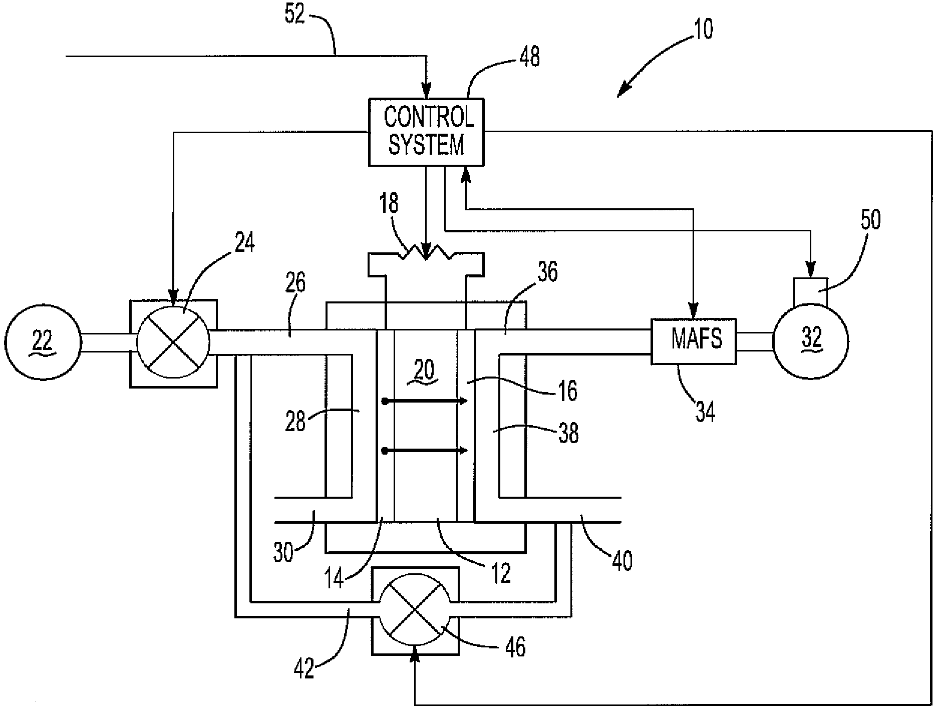
"The present invention provides a fuel cell system with improved shutdown capabilities. The system includes an anode and a cathode with flow paths connected to a gas source and a gaseous fuel source. An electrolyte is positioned between the anode and cathode, and an electrical load is connected in series with the anode and cathode. In operation, hydrogen is flowed through the anode flow path where it dissociates into protons and electrons, which are conducted through the electrolyte to the cathode. Oxygen, such as air containing oxygen, is flowed through the cathode flow path. The hydrogen protons and electrons combine with the oxygen to form water, which is exhausted from the cathode flow path. During shutdown, the control system changes the stoichiometric ratio at the cathode to less than or equal to one, which depletes the outflow of oxygen and reduces the charge on the electrolyte. The now oxygen-depleted gas flows through the anode flow path to purge the anode of fuel. This effectively reduces the charge on the electrolyte to zero or near zero."

Problems solved by technology

Over time the charge on the fuel cell membrane following fuel cell shutdown may result in degradation of the fuel cell.
The use of such stored nitrogen or helium, however, is disadvantageous where the fuel cell is used in a motor vehicle since the purged gas must be replenished periodically.

Method used


Image

  • Fuel system with improved fuel cell shutdown
  • Fuel system with improved fuel cell shutdown

Examples


Embodiment Construction

[0017]With reference to the drawing, a preferred embodiment of a fuel cell system 10 according to the present invention is shown and includes a fuel cell 12. The fuel cell 12 includes an anode 14 and a cathode 16. An electrical load 18 is connected in series between the anode 14 and cathode 16. The load 18 may comprise, for example, a battery, electric motor for an electric vehicle or other electrical system.

[0018]An electrolyte 20 is sandwiched in between the anode 14 and cathode 16. The electrolyte 20 comprises a proton conducting polymer membrane which separates the anode 14 from the cathode 16. Furthermore, although only a single anode 14, single cathode 16 and single electrolyte 20 is illustrated in the drawing, it will be understood that in a typical application the overall fuel cell 12 includes a plurality of layers in order to obtain the desired voltage output from the fuel cell 12.

[0019]A fuel source 22, such as a source of compressed hydrogen, is connected through a valve ...


PUM

PropertyMeasurementUnit
electrical loadaaaaaaaaaa
electric poweraaaaaaaaaa
electrical poweraaaaaaaaaa

Abstract

A fuel cell system having a fuel cell with an anode and a cathode wherein both the cathode and anode each have a flow path with an inflow and outflow. A gaseous source containing oxygen is connected to the inflow of the cathode flow path while a gaseous fuel source is connected to the inflow of the anode flow path. Upon shutdown of the fuel cell, a control system reduces the stoichiometric ratio at the anode to less than or equal to one to thereby deplete the oxygen from the gas at the cathode. A normally closed valve is fluidly connected between the cathode outflow and the anode inflow. The control system opens the valve upon shutdown of the fuel cell to thereby purge the fuel from the anode flow path with the oxygen depleted outflow from the cathode flow path.

Description

CROSS-REFERENCE TO RELATED APPLICATIONS[0001]This application claims priority of U.S. Provisional Patent Application Ser. No. 60 / 740,756 filed Nov. 30, 2005, which is incorporated herein by reference.BACKGROUND OF THE INVENTION[0002]I. Field of the Invention[0003]The present invention relates generally to fuel cells and, more particularly, to a fuel cell with an improved fuel cell shutdown.[0004]II. Description of Related Art[0005]Although different types of electrical energy storage devices may be utilized for powering electric motor vehicles, there has been an increased interest in the use of fuel cells to provide the electric power for such electric vehicles. Such fuel cells contain both a cathode and an anode, each of which has a gaseous flow path. A gaseous fuel, such as hydrogen, is coupled to the flow path of the anode while a reactant gas, such as air containing oxygen, flows through the cathode flow path. An electrolyte is positioned in between the anode and cathode flow pa...

Claims


Application Information

Patent Timeline
Patent Type & Authority Patents(United States)
IPC IPC(8): H01M8/04
CPCH01M8/04231H01M2008/1095Y02E60/50
Inventor SPARE, BRADLEY LANDON
Owner TOYOTA MOTOR CO LTD
Learn More