Downhole application for a backpressure valve

a backpressure valve and application technology, applied in the field of coiled tubing, can solve the problems of throttling of the valve, high cost, and difficulty in ensuring the safety of the valve, and achieve the effect of preventing the valve from throttling

Inactive Publication Date: 2010-12-28
SCHLUMBERGER TECH CORP
View PDF12 Cites 9 Cited by
  • Summary
  • Abstract
  • Description
  • Claims
  • Application Information

AI Technical Summary

Benefits of technology

[0011]A backpressure valve is provided to substantially maintain controlled pressure in coiled tubing disposed within a well. The valve may have a housing with an uphole portion for coupling to the coiled tubing and a downhole portion for coupling to a downhole tool. A valve is disposed within the housing at an interface of the uphole and downhole portions. The valve may be employed to open and close in order to provide pressure control as directed by an operator. Additionally, a pressure generating mechanism is disposed within the downhole portion to substantially prevent throttling of the valve when open.

Problems solved by technology

Exploring, drilling and completing hydrocarbon and other wells are generally complicated, time consuming and ultimately very expensive endeavors.
While more sophisticated well architecture may increase the likelihood of accessing underground hydrocarbons, the nature of such wells presents particular challenges in terms of well access and management.
However, providing downhole access to wells of such challenging architecture may require more than simply dropping a wireline into the well with the applicable tool located at the end thereof.
However, in many cases, the downhole application and tool may require pressurization that substantially exceeds the amount of pressure required to merely ensure coiled tubing integrity.
Unfortunately, the described technique of employing a pulse generating tool, such as the indicated locating tool, downhole of a backpressure valve, remains impractical.
This is due to the fact that a conventional backpressure valve is subject to periodic throttling of the valve between open and closed positions with the closed position killing any signal from the locating tool.
That is, once uphole pressure cracks open the backpressure valve, an equilibrium between pressure at either side of the valve is naturally sought, allowing the valve and seat to periodically open and close relative to one another in an uncontrolled manner.
Thus, as a practical matter, where a pressure differential between the well and coiled tubing is significant enough to require use of a backpressure valve, hydraulic pulse communication from below the valve remains an unavailable option.

Method used


Image

  • Downhole application for a backpressure valve
  • Downhole application for a backpressure valve
  • Downhole application for a backpressure valve

Examples


Embodiment Construction

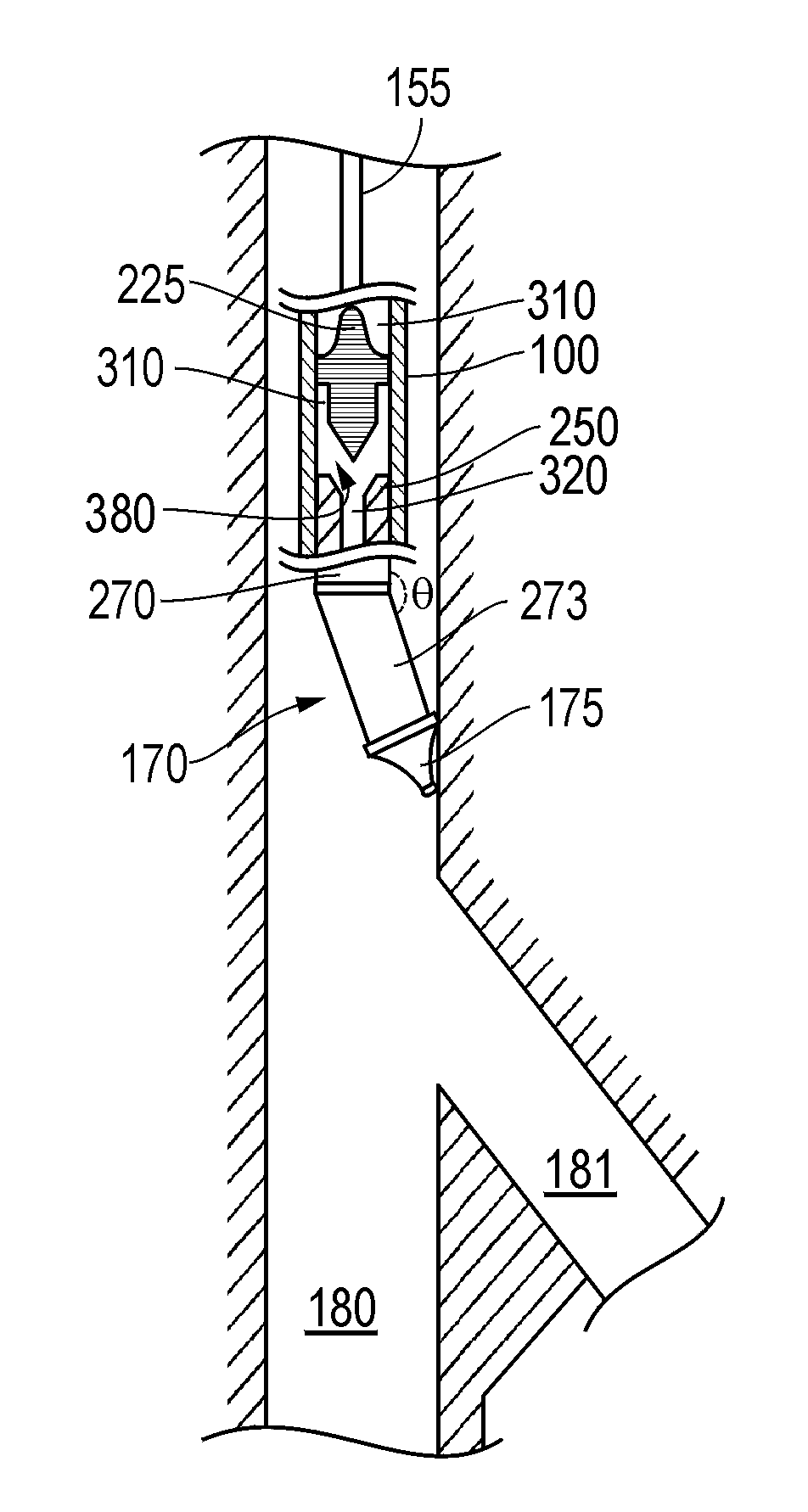
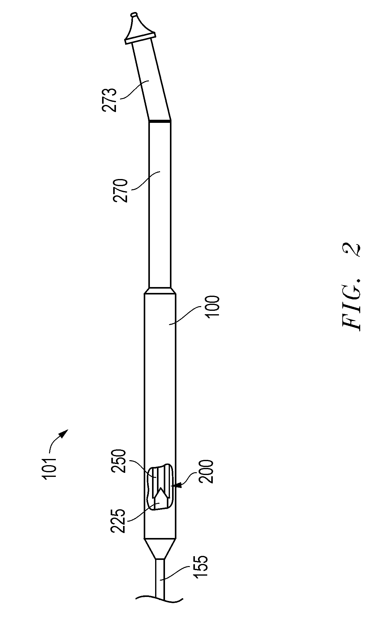
[0020]Embodiments are described with reference to certain coiled tubing operations employing a downhole tool configured to communicate with surface equipment and the operator through the coiled tubing via pressure pulses. An embodiment of a backpressure valve with a pressure generating mechanism incorporated therein is coupled to the downhole tool that is of a configuration to allow pressure pulse communication therethrough. In one embodiment, the downhole tool is a locating tool in the form of a multilateral tool for locating a horizontal or lateral leg off of a primary borehole. However, a variety of other locating tools or other tool types employing pressure pulse communication may be employed. Regardless, embodiments of the backpressure valve are configured to help ensure that pressure signal communication between the downhole tool and surface equipment may be permitted and maintained without signal interruption by throttling of the backpressure valve.

[0021]Referring now to FIG....


PUM


Abstract

A backpressure valve. The backpressure valve may be configured to maintain a substantially controlled pressure in bottom hole assembly while simultaneously being compatible with a pressure pulse tool downhole thereof. The backpressure valve includes pressure generating capacity below its internal valve assembly so as to avoid the tendency of the assembly to throttle open and closed. Furthermore, the pressure generation is achieved in a manner avoiding cavitation. As a result, once the backpressure valve is opened, the pressure pulse tool is able to reliably communicate with surface equipment at the oilfield.

Description

CROSS-REFERENCE TO RELATED APPLICATIONS[0001]This application claims priority to and is a Continuation in Part of U.S. patent application Ser. No. 12 / 135,682 filed on Jun. 9, 2008, which is incorporated herein by reference.FIELD OF THE INVENTION[0002]Embodiments described relate to coiled tubing for use in hydrocarbon wells. In particular, embodiments of coiled tubing are described utilizing a backpressure valve at a downhole end thereof to maintain a pressure differential between the coiled tubing and an environment in a well. Additionally, such coiled tubing may also be compatibly employed with pressure signal generating tools positioned downhole of the valve.BACKGROUND OF THE RELATED ART[0003]Exploring, drilling and completing hydrocarbon and other wells are generally complicated, time consuming and ultimately very expensive endeavors. As a result, over the years, well architecture has become more sophisticated where appropriate in order to help enhance access to underground hydr...

Claims


Application Information

Patent Timeline
Patent Type & Authority Patents(United States)
IPC IPC(8): E21B21/10
CPCE21B17/20E21B21/08E21B41/0035E21B47/18
Inventor TUNC, GOKTURKXU, ZHENG RONGSCHORN, PATRICKLEISING, LAWRENCE J.
Owner SCHLUMBERGER TECH CORP
Why Eureka
Try Eureka