System and method for utilizing stored electrical energy for VTOL aircraft thrust enhancement and attitude control

a technology of stored electrical energy and thrust enhancement, applied in the direction of vertical landing/take-off aircraft, aircraft navigation control, transportation and packaging, etc., can solve the problems of low efficiency, low efficiency, and low observability of aircraft, so as to maximize engine efficiency and performance capability

Active Publication Date: 2010-12-28
AURORA FLIGHT SCI CORP
View PDF50 Cites 107 Cited by
  • Summary
  • Abstract
  • Description
  • Claims
  • Application Information

AI Technical Summary

Benefits of technology

[0016]An object of the present invention is to substantially solve at least the above problems and / or disadvantages and to provide at least the advantages described below. Accordingly, it is an object of the present invention to provide a short take-off and landing / vertical take-off and landing aircraft (STOL / VTOL A / C) that utilizes an internal combustion engine for vertical and horizontal flight, and an electric fan engine for vertical flight to maximize engine efficiency and performance capability.
[0017]It is an object of the present invention to provide a gas turbine engine, in the form of either a turbo jet or turbo fan, to provide vertical and horizontal thrust. The gas turbine engine tilts, from a substantially vertical position, to a substantially horizontal position. Either the entire engine or just the engine nozzle may be tilted. Additional vertical thrust is provided by an electric fan engine(s). Utilizing two different types of engines maximizes the performance of each for their intended use. As a result, the STOL / VTOL A / C according to an embodiment of the present invention operates at greater engine efficiency over greater operating conditions than any other STOL / VTOL A / C provided in the prior art.
[0018]It is an object of the present invention to provide an STOL / VTOL A / C that uses electrically driven fans that can obtain their power either from batteries or from a generator mounted on the main engine(s). Accordingly, high power density batteries can be used to power the fans, and in one embodiment the batteries are mounted as an integral part of the fan units to make a fan module that can be easily removed and replaced for servicing. This minimizes the length of the high power wiring to reduce losses and save weight. Alternatively, the batteries can be installed around the outside of the fan duct, but in thermal contact with the duct. This uses the fan air flow through the duct to cool the batteries during fan operation, while incurring no loss of fan. The batteries can either be recharged while the aircraft is on the ground, or they may be recharged during the flight with power from a generator mounted on the main turbine engine(s). Further still, because forward flight duration is relatively longer than periods of hovering, the charging power is a small fraction of the flight power

Problems solved by technology

The transition from vertical to horizontal flight must be done carefully, especially in non-rotating wing aircraft, because too fast a transition will leave the aircraft with an insufficient amount of air moving over the wings, and no lift will be generated, and the aircraft will fall, like a rock.
Another problem that all the aircraft shown in FIGS. 1A-1C exhibit is that of high observability.
Generally, this is a relatively inefficient design.
If loiter operations are considered, the problem is even more pronounced.
If a gas turbine engine has been designed to produce a large amount of thrust for vertical take-off, it will not operate efficiently with lesser amounts of thrust for horizontal flight, and will operate with even less efficiency at loiter speeds.
Thus, the prior art of aircraft that are characterized as STOL / VTOL A / C suffer from either extremely complicated means of transferring power from one engine to both vertical and horizontal propulsion systems, or use only internal combustion engines to provide both vertical and horizontal engines, thereby being inherently inefficient in their operation.

Method used


Image

  • System and method for utilizing stored electrical energy for VTOL aircraft thrust enhancement and attitude control
  • System and method for utilizing stored electrical energy for VTOL aircraft thrust enhancement and attitude control
  • System and method for utilizing stored electrical energy for VTOL aircraft thrust enhancement and attitude control

Examples


Embodiment Construction

[0060]Several embodiments of the present invention will now be described in detail with reference to the annexed drawings. In the drawings, the same or similar elements are denoted by the same reference numerals even though they are depicted in different drawings.

[0061]Normal short take-off and landing / vertical take-off and landing aircraft (STOL / VTOL A / C) require large amounts of thrust or power from the engines for take-off and landing. This means that the engines are much larger and heavier than needed for cruise flight, and they are also operating at low throttle settings for most of the flight. On a gas turbine engine, this low throttle setting results in higher specific fuel consumption than a normal aircraft would have.

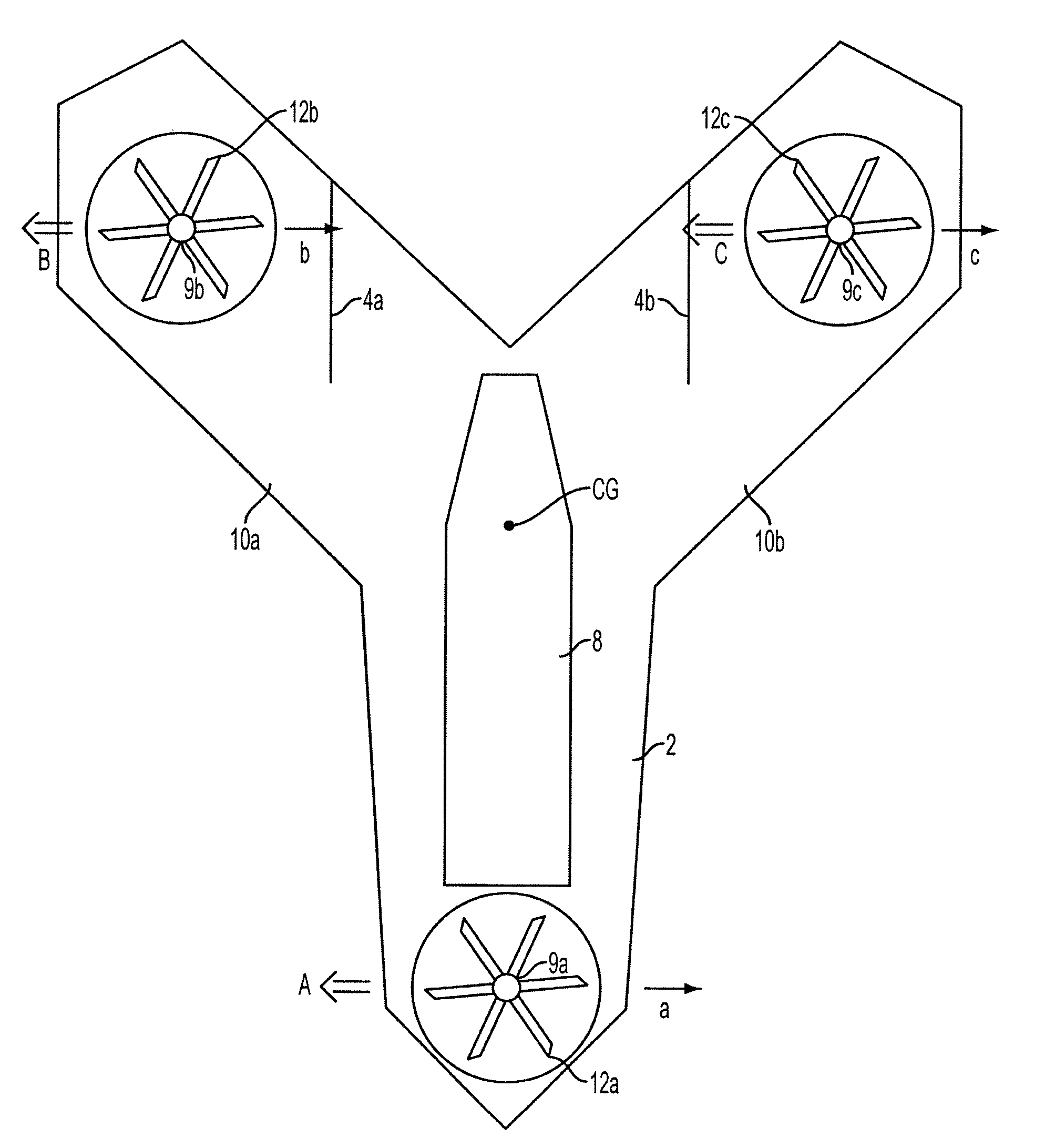
[0062]The present invention provides a means of efficiently obtaining the high thrust for takeoff and landing while retaining a smaller, lighter and more fuel efficient main engine. Accordingly, a STOL / VTOL A / C according to an embodiment of the present inventio...


PUM


Abstract

A system and method are provided for a short take-off and landing / vertical take-off and landing aircraft that stores required take-off power in the form of primarily an electric fan engine, and secondarily in the form of an internal combustion engine, wherein the combined power of the electric fan and internal combustion engines can cause the STOL / VTOL A / C to take-off in substantially less amount of time and space than other STOL / VTOL A / C, and further wherein the transition from vertical to horizontal thrust is carefully executed to rapidly rise from the take-off position to a forward flight position, thereby minimizing the necessity for a larger electric fan engine.

Description

DOMESTIC PRIORITY[0001]The present application claims priority under 35 U.S.C. §119(e) to U.S. Provisional Patent Application Ser. No. 60 / 637,670, filed Dec. 22, 2004, the entire contents of which are expressly incorporated herein by reference.BACKGROUND OF THE INVENTION[0002]1. Field of the Invention[0003]The invention relates to short take-off and landing aircraft and vertical takeoff and landing aircraft (STOL / VTOL A / C). More particularly, the invention relates to a system and method for combining and transferring power between an electric fan engine and an internal combustion engine to maximize take-off, horizontal and hovering flight performance.[0004]2. Description of the Related Art[0005]FIGS. 1A-1C illustrate perspective views of several typical aircraft with tilt engine capabilities. The use of tilt engines in aircraft is well known to those of ordinary skill in the art. The principle benefit of a tilt engine is a shortened or vertical take-off capability. Vectoring the thr...

Claims


Application Information

Patent Timeline
Patent Type & Authority Patents(United States)
IPC IPC(8): B64C15/12
CPCB64C15/00B64C29/0025B64C29/0033B64C29/0041B64C29/0083
Inventor PARKS, ROBERT
Owner AURORA FLIGHT SCI CORP
Why Eureka
Try Eureka