Rotary lobe pump

a rotary lobe and cylinder technology, applied in the direction of rotary/oscillating piston pump components, machines/engines, liquid fuel engines, etc., can solve the problems of contaminated pumped materials, time-consuming and laborious, and loss of production, so as to reduce the risk of insert jamming, improve sealing performance, and simplify the molding of the housing

Active Publication Date: 2010-12-28
ITT MFG ENTERPRISES LLC
View PDF9 Cites 6 Cited by
  • Summary
  • Abstract
  • Description
  • Claims
  • Application Information

AI Technical Summary

Benefits of technology

[0008]External surfaces of the housing may include raised portions for locating the insert within the outer casing. The dimensional accuracy of these raised portions may then be accurately controlled. External surfaces of the housing may also include stiffening ribs.
[0019]The pump body may further comprise a closing plate for maintaining the insert within the outer casing. In this case, the output shafts may each be provided with a resilient means, such as a compression spring or washer, for urging the insert against the closing plate. The closing plate may be provided with thrust bearings so as to avoid friction between the rotors and the closing plate.

Problems solved by technology

A problem associated with this cleaning and sterilization process is that it is time consuming and prone to errors.
Any errors in the cleaning process may result in contamination of the pumped material and / or loss of production.

Method used


Image

  • Rotary lobe pump
  • Rotary lobe pump
  • Rotary lobe pump

Examples


Embodiment Construction

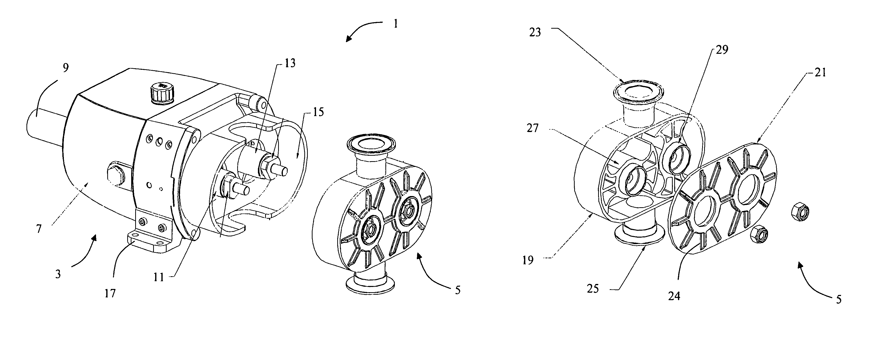
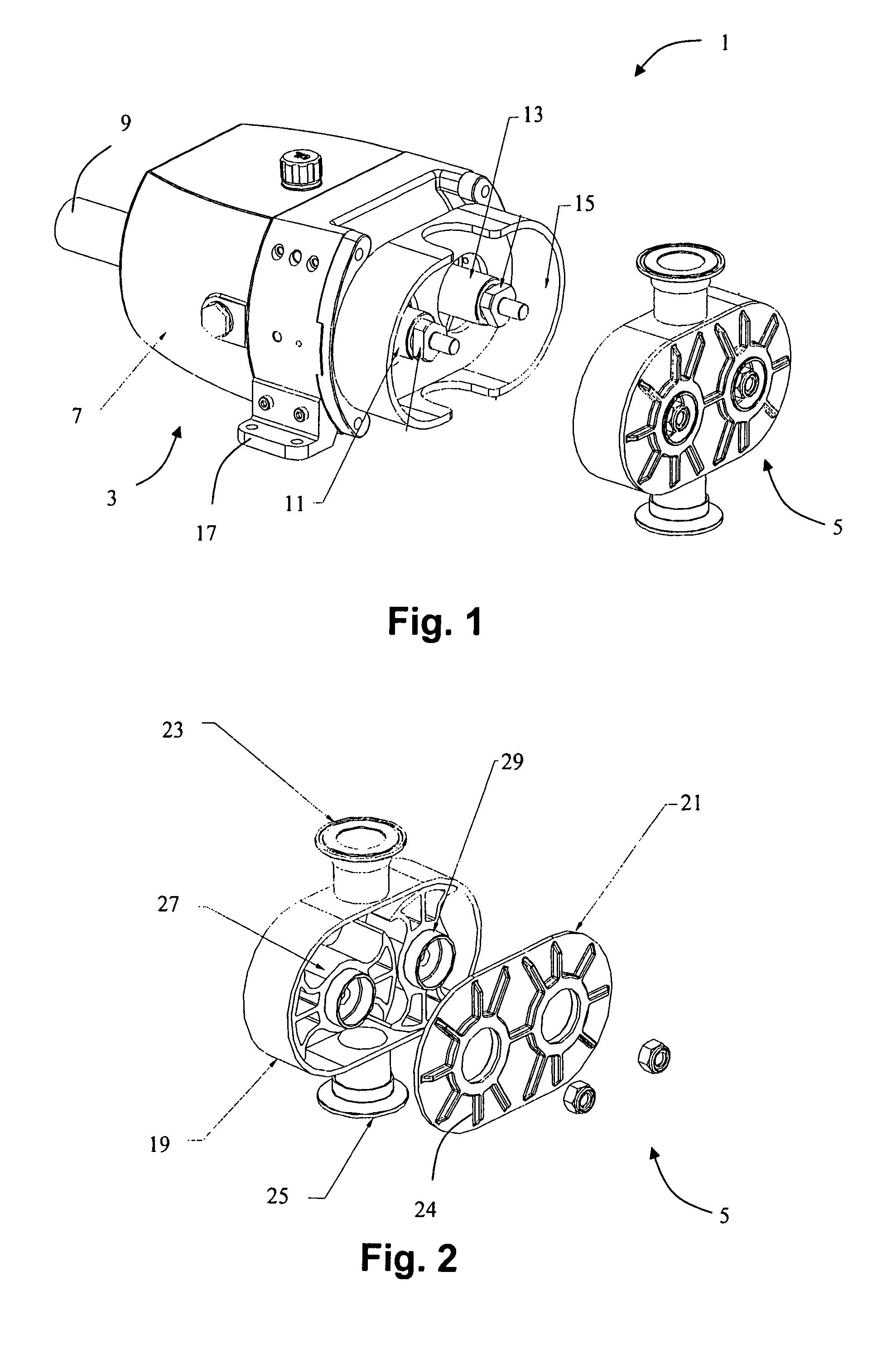
[0029]The invention provides a rotary lobe pump comprising a pump body and an insert. The pump body includes the components of the pump that do not generally come into contact with the pumped material. The insert is a plastic component that includes the components of the pump that do come into contact with the pumped material, namely the pumping chamber and the lobed rotors. The insert is closely (to avoid rattling) received in and supported by an outer casing of the pump body.

[0030]FIG. 1 shows a rotary lobe pump 1 according to the invention. The pump 1 includes a pump body 3 and a plastic insert 5.

[0031]The pump body 3 comprises drive means in the form of a gearbox 7. The gearbox 7 has an input shaft 9 at one end and two output shafts 11, 13 at the other end. The gearbox 7 is arranged so that the output shafts 11, 13 rotate at the same angular speed but in opposite directions. The output shafts 11, 13 are provided with keys (not shown) for rotationally driving other elements.

[0032...


PUM


Abstract

A rotary lobe pump comprises a pump body having a driving means and an outer casing, and an insert that can be replaced. The replaceable insert comprises a housing formed of a plastic material and having an inlet port, an outlet port and internal surfaces defining a pumping chamber. The replaceable insert also includes a pair of lobed rotors arranged for rotation within the pumping chamber. The housing includes apertures through which the lobed rotors may be rotationally driven, so that the lobed rotors mesh together for pumping a fluid from the inlet port to the outlet port.

Description

CROSS-REFERENCE[0001]Applicant claims priority from British patent application No. 0616034.5 filed 11 Aug. 2006.BACKGROUND OF THE INVENTION[0002]This invention relates to rotary lobe pumps. Rotary lobe pumps are used in industry for positive-displacement pumping of foodstuffs, pharmaceuticals, and other similar materials. When handling these materials, it is important that cross-contamination and chemical interaction with other materials are avoided.[0003]Known rotary lobe pumps include provision for dismantling by the user. In this way, components of the pump that come into contact with the pumped material can be cleaned and sterilized between different batches. A problem associated with this cleaning and sterilization process is that it is time consuming and prone to errors. Any errors in the cleaning process may result in contamination of the pumped material and / or loss of production.[0004]In general, components of rotary lobe pumps are manufactured with high dimensional accuracy...

Claims


Application Information

Patent Timeline
Patent Type & Authority Patents(United States)
IPC IPC(8): F01C1/18F01C1/24F03C2/00
CPCF04C2/126F04C2240/10F05C2225/00F04C2240/80F04C2240/30
Inventor BISHOP, LEEYOUNG, MICHAEL
Owner ITT MFG ENTERPRISES LLC
Why Eureka
Try Eureka