Power converter, power system provided with same, and mobile body

a technology of power converter and power system, which is applied in the direction of motor/generator/converter stopper, dynamo-electric converter control, instruments, etc., can solve the problems of yield, and reducing the accuracy of current detector, so as to inhibit the influence of magnetic flux, small power converter, and large power module size

Inactive Publication Date: 2010-12-28
HITACHI LTD
View PDF24 Cites 6 Cited by
  • Summary
  • Abstract
  • Description
  • Claims
  • Application Information

AI Technical Summary

Benefits of technology

[0018]Herein, the present invention provides a small power converter which is able to accurately control electric power, and an electric power system and mobile body equipped with the power converter. Furthermore, the present invention provides a power converter equipped with a small current detector which is able to accurately detect current, and an electric power system and mobile body equipped with the power converter.
[0140]According to the aforementioned mobile body, because the above-mentioned power converter, which is small and accurately controls electric power, is used as a power converter for a mobile body, the mobile body can be made inexpensive, fuel efficiency and travel distance per one battery charge can be improved, and space for mounting the power converter can be reduced.

Problems solved by technology

Therefore, it is considered that in the above-mentioned mounting method, the difference of linear expansion coefficients between the Hall element and the resin formed body causes thermal stress, which results in permanent deformation of the Hall element, thereby decreasing the accuracy of the current detector.
However, in this mounting method, it is considered that if the thickness of the adhesion layer or insulation layer is not uniform, intervals between the Hall element and the current-carrying conductor become nonuniform, causing the accuracy of the current detector to decrease.
As a result, it is presumed that a production yield will decrease, causing production costs to increase.

Method used


Image

  • Power converter, power system provided with same, and mobile body
  • Power converter, power system provided with same, and mobile body
  • Power converter, power system provided with same, and mobile body

Examples


embodiment 1

[0208]A first embodiment of the present invention will be explained by referring to FIGS. 1 through 9. What is explained as an example in this embodiment is a power converter (inverter) which is incorporated in a motor drive system of an electric car that is driven by a motor as the vehicle's only drive source, and which converts DC power outputted from a battery, which is a power storage means, into three-phase AC power and supplies the power to the motor.

[0209]FIG. 9 is a schematic diagram showing the configuration of an electric car equipped with a motor drive system which incorporates a power converter according to this embodiment. In FIG. 9, 18 denotes a vehicle body. At the front of the vehicle body 18, front wheels having an axle 20 and wheels 19a and 19b attached to both ends of the axle 20 are rotatably mounted. At the rear of the vehicle body 18, rear wheels having an axle 22 and wheels 21a and 21b attached to both ends of the axle 22 are rotatably mounted.

[0210]A motor 5 ...

embodiment 2

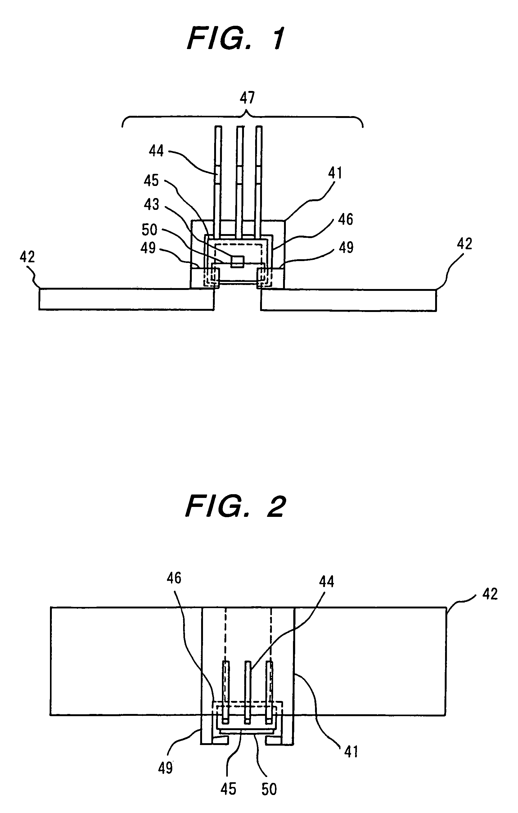
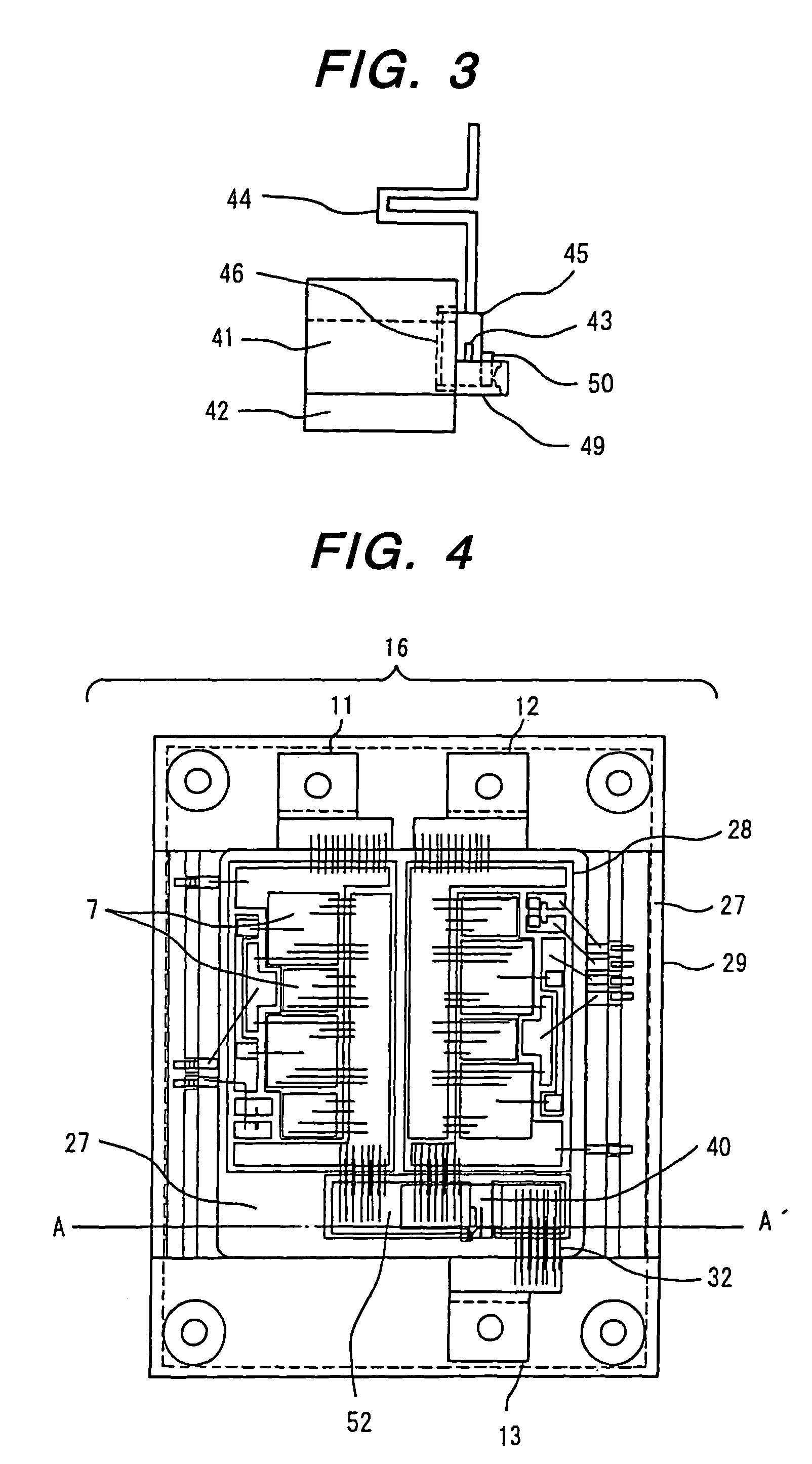
[0251]A second embodiment of the present invention will be explained with reference to FIGS. 10 through 12. FIGS. 10 through 12 show the configuration of a current detector incorporated into a power converter of this embodiment. This embodiment is an altered example of the first embodiment. In this embodiment, a magnetic detecting semiconductor element 43 is fixed onto the printed wiring board 53 which is configured such that a plurality of laminated wiring sheets 54, each of which consists of a resin insulation layer and a laminated copper foil, are laminated; and a magnetic detecting unit 47 is provided in which the magnetic detecting semiconductor element 43 has electrical connections with the laminated wiring sheets 54 via aluminum wires, and connection terminals 44 have electrical connections with the laminated wiring sheets 54. The magnetic detecting semiconductor element 43 is covered with molded resin 45.

[0252]For example, the laminated wiring sheets 54 are disposed together...

embodiment 3

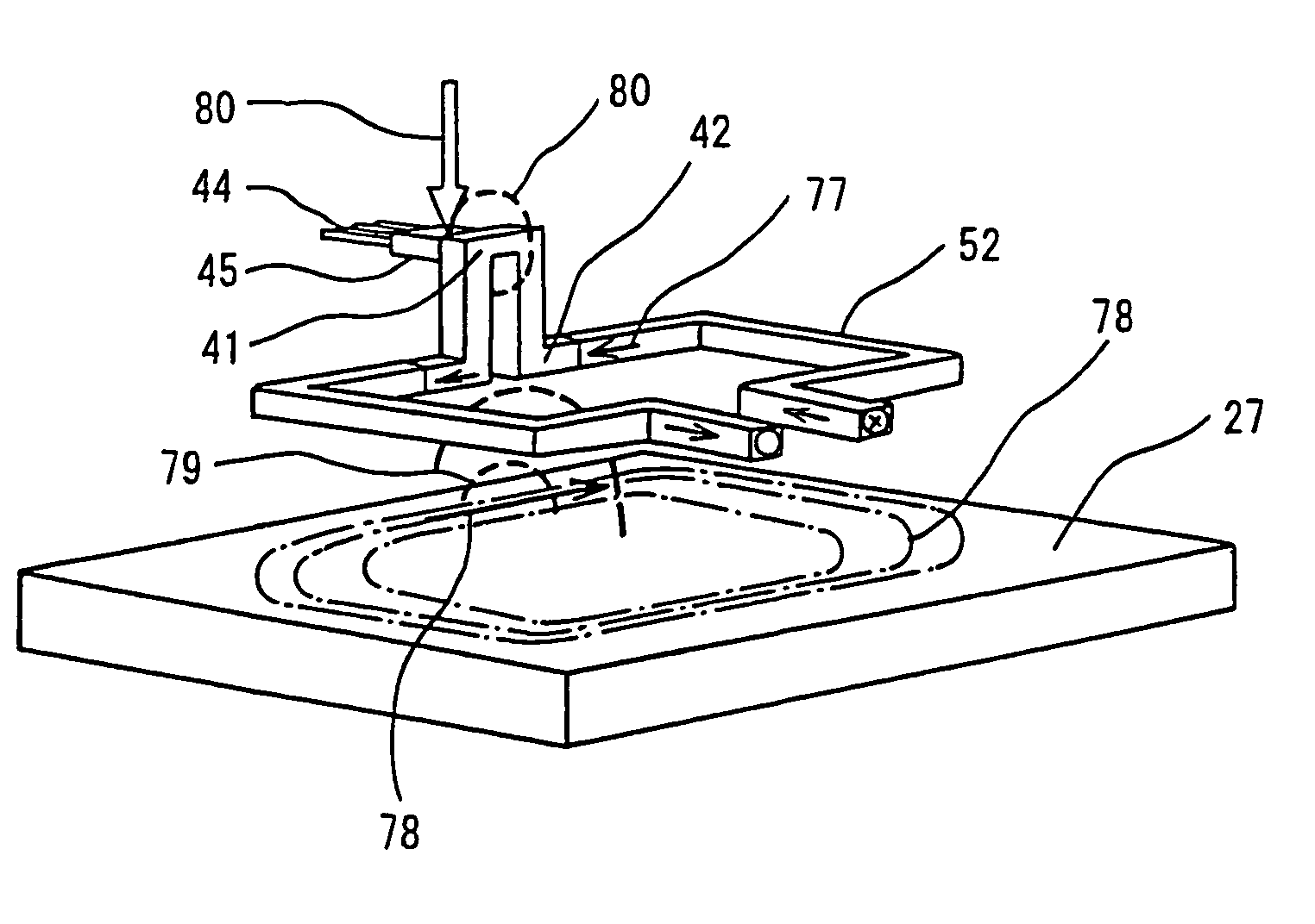
[0257]A third embodiment of the present invention will be explained with reference to FIGS. 13 through 15. FIGS. 13 through 15 show the configuration of a current detector incorporated into a power converter of this embodiment. This embodiment is an altered example of the first embodiment. In this embodiment, a magnetic detecting unit 47 configured in the same manner as the first embodiment is provided, and a part of the magnetic detecting unit 47 is contained in the depression 46 of the detection conductor 41, which is provided in the same manner as the first embodiment, so that connection terminals 44 extend in the same direction as shown in the first embodiment.

[0258]The bottom portion of the nearly letter-U shaped resin formed body 57 having a protruding / recessed portion 58 is inserted into the cavity of the detection conductor 41 from one side of the detection conductor 41 which is the opposite side of the magnetic detecting unit 47 side, and is engaged with the detection condu...


PUM


Abstract

To provide a power converter equipped with a current detector which is small and can carry out highly accurate current detection, in the power converter equipped with a power module 16 having a power controlling semiconductor element 7 disposed on the power module base 27 with a ceramic substrate 28 interposed, and a control unit 26 for controlling the operation of the power controlling semiconductor element 7, a current detector 40 having a magnetic detecting unit 47 which is disposed in the detection conductor 11, electrically connected to the power controlling semiconductor element 7 and disposed on the power module base 27 with the ceramic substrate 28 interposed, and has a magnetic detecting semiconductor element 43 electrically connected to the control unit 26 is provided in the power module 16; and relative distance between the detection conductor 11 and the power module base 27 is larger than the relative distance between the current detection electrode 42 and the power module base 27.

Description

CLAIM OF PRIORITY[0001]The present application claims priority from Japanese application serial No. 2002-102916, filed on Apr. 4, 2002, and PCT International Application, PCT / JP03 / 0434(filed on Apr. 3, 2004, the content of which is hereby incorporated by reference into this application.BACKGROUND OF THE INVENTION[0002]The present invention relates to a power converter for controlling electric power supplied to a load, and an electric power system and a mobile body equipped with the power converter.[0003]In an electric power system for supplying electric power to a load, a power converter is controlled according to load current flowing through the load, thereby controlling electric power supplied to the load. To do so, the electric power system is equipped with a current detector for detecting the load current flowing through the load.[0004]Conventionally, in an electric power system for supplying electric power to a load, such as a motor drive system for converting direct current (D...

Claims


Application Information

Patent Timeline
Patent Type & Authority Patents(United States)
IPC IPC(8): H01L23/48H01L23/52H01L29/40H02M7/00
CPCH02M7/003H01L2924/3025G01R15/202G01R15/207H01L2224/48091H01L2224/48227H01L2224/48472H01L2224/73265H02M2001/0009H01L2924/13091H01L2924/13055H01L2224/45124H01L2924/00014H01L2924/00H02M1/0009
Inventor NAKATSU, KINYAYAHATA, KOICHITAKAHASHI, MASATOIWANAKA, MITSUFUMISAITO, RYUICHIHAMADA, HARUKI
Owner HITACHI LTD
Why Eureka
Try Eureka