Piezoelectric ultracapacitor

a technology of ultracapacitors and elastomers, applied in capacitor collector combinations, capacitor dielectric layers, generators/motors, etc., can solve the problems of dielectric elastomers operated in generator mode, however, not themselves creating energy, and achieving the effect of efficiently utilizing energy in physical motion

Inactive Publication Date: 2010-12-28
MICALLEF JOSEPH A
View PDF10 Cites 28 Cited by
  • Summary
  • Abstract
  • Description
  • Claims
  • Application Information

AI Technical Summary

Benefits of technology

[0005]These and other needs are satisfied by the present invention, which employs a piezoelectric ultracapacitor to harness efficiently the energy in physical motion, such as walking, driving or vibrating. While some have attempted in the past to use piezoelectrics for energy generation, the extremely small electrical current piezoelectric materials are capable of producing have limited those efforts. Ultracapacitors, of course, have been known and used in various contexts for energy storage. They have not, to the inventor's knowledge, been used for energy generation purposes. The combination of piezoelectric and ultracapacitor technologies, particularly in the combinations described as examples herein, provides extraordinary efficiencies in the conversion of movement to electricity.
[0006]Moreover, the current invention may be used in conjunction with other power generation technologies, such as fuel cells and solar cells, to increase the efficiencies of those technologies. For example, the piezoelectric ultracapacitors of the present invention may be coupled to the electrodes of a fuel cell, creating an electric potential across them and lowering the activation energy necessary to invoke the chemical reactions at the heart of the fuel cell.
[0008]An elastomeric piezoelectric ultracapacitor embodiment is also disclosed. An elastomer is a polymer that exhibits the characteristic of elasticity. It has been known for some time that dielectric elastomers may be configured to operate in a “generator mode.” In generator mode the dielectric elastomer operates like a variable capacitor, and amplifies the energy of charge placed on a pair of compliant electrodes, formed on opposite sides of the elastomer, when the elastomer is in a compressed state. See, for example, R. Pelrine et al., “Dielectric Elastomers: Generator Mode Fundamentals And Its Applications”, Smart Structures and Materials 200; EAPAD, vol. 4329, pp. 148-156, 2001, all parts of which are hereby incorporated by reference for all purposes. Dielectric elastomers operated in a generator mode, however, do not themselves create energy. Rather, they merely amplify energy placed on the dielectric elastomer when it is in a compressed state. An elastomeric piezoelectric ultracapacitor employs generator mode techniques to further increase the power generation capabilities of an piezoelectric ultracapacitor.

Problems solved by technology

While some have attempted in the past to use piezoelectrics for energy generation, the extremely small electrical current piezoelectric materials are capable of producing have limited those efforts.
Dielectric elastomers operated in a generator mode, however, do not themselves create energy.

Method used


Image

  • Piezoelectric ultracapacitor
  • Piezoelectric ultracapacitor
  • Piezoelectric ultracapacitor

Examples


Embodiment Construction

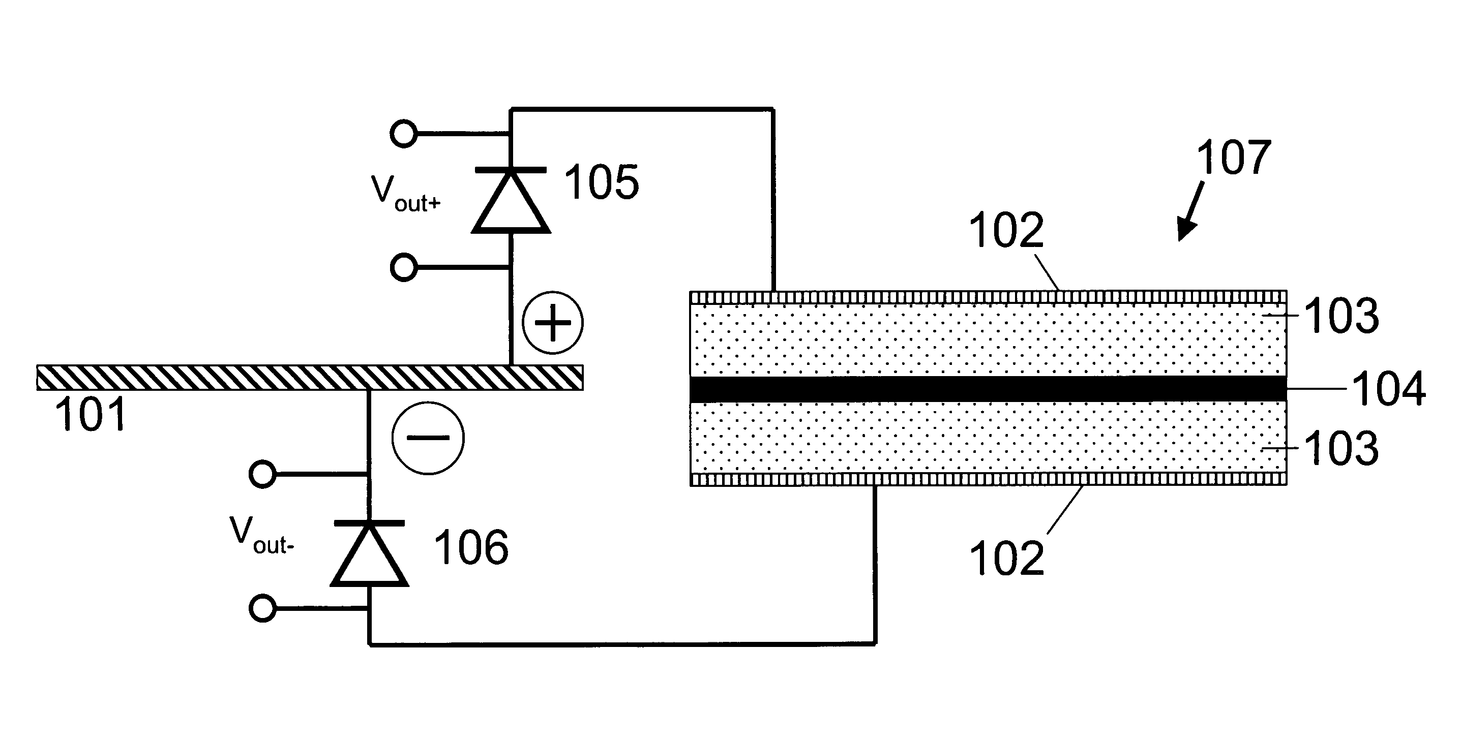
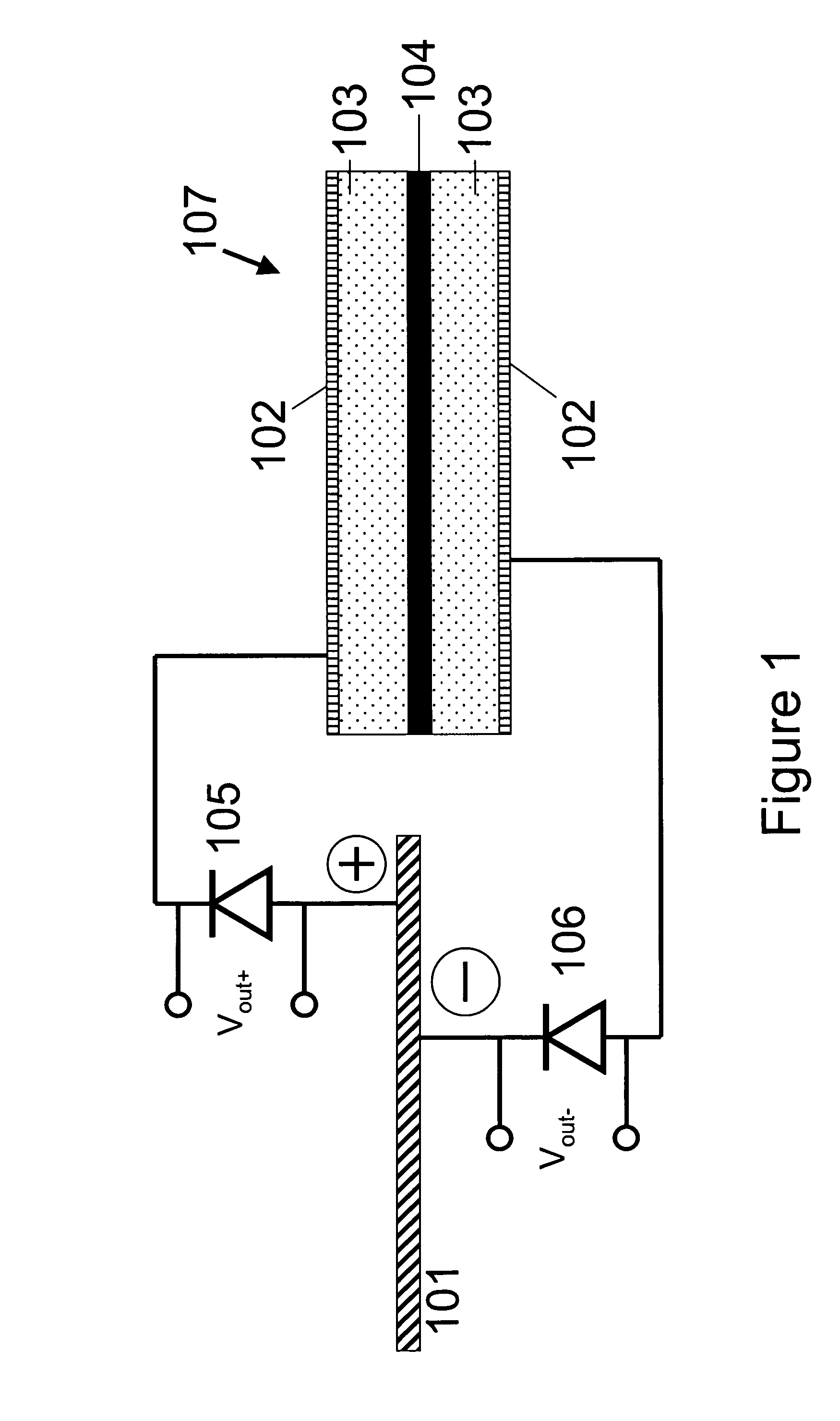
[0025]Referring to FIG. 1, piezoelectric element 101 is coupled to ultracapacitor 107 through diodes 105 and 106. Piezoelectric element 101 can be formed of one or more portions of any suitable piezoelectric material, such as polyvinylidene difluoride (known as “PVDF”) or lead zirconate titanate (often referred to as “PZT”). The invention is not limited to the use of these materials, though it is believed that the flexible nature of these two piezoelectric materials provides some protection from cracking or other damage during use. Flexible piezoelectric materials are therefore preferred.

[0026]Moreover, experiments have shown that the power generation capabilities is not greatly enhanced by the use of PZT (which is inherently capable of creating higher voltages than PVDF); PVDF is therefore preferred due to its lower cost. Such materials are known and commercially available from many different sources. PVDF, for example, is available commercially under the trade names KYNAR® and KYN...


PUM


Abstract

A piezoelectric ultracapacitor is disclosed capable of converting the kinetic energy of ordinary motion into an electrical potential. Multiple piezoelectric ultracapacitors may be configured together to provide an increased output voltage and various materials may advantageously be used. The piezoelectric ultracapacitor of the present invention may be used in various contexts, including power generation, switching and control and memory. An elastomeric piezoelectric ultracapacitor, along with methods of making and operating such a device, is also disclosed. The elastomeric piezoelectric ultracapacitor utilizes the voltage generation capabilities of a piezoelectric ultracapacitor and the generator mode operation of an elastomer actuator, combined and cooperating in novel ways, to provide improved energy generation capabilities.

Description

[0001]This application is a continuation-in-part of application Ser. No. 11 / 849,326, filed Sep. 3, 2007, and of application Ser. No. 11 / 548,282, filed Oct. 10, 2006, both of which are hereby incorporated by reference in their entirety for all purposes.BACKGROUND OF THE INVENTION[0002]The generation of energy is a substantial concern to governments, individuals and research bodies around the world because of the difficulty in securing sufficient fuels to meet rising energy demand and the many environmental hazards associated with the generation of power and the acquisition of fuel stocks. One need only consider the Middle East or the tailpipe of an automobile to begin to appreciate the problems involved with the current approach to energy generation.[0003]Many have attempted to develop acceptable alternatives to fossil or nuclear fuels, with limited success. Solar, wave and wind energy systems, for example, provide mechanisms by which electrical energy can be generated without the us...

Claims


Application Information

Patent Timeline
Patent Type & Authority Patents(United States)
IPC IPC(8): H01L41/107H02N2/18
CPCH01G9/028H01G9/07H01G9/155H01G17/00H02N2/18Y02E60/13Y02T10/7022Y02T10/70H01G11/56H01G11/08
Inventor MICALLEF, JOSEPH A.
Owner MICALLEF JOSEPH A
Why Eureka
Try Eureka