Apparatus for moving curved-surface mirror, exposure apparatus and device manufacturing method
a technology of curved surfaces and mirrors, applied in the direction of mountings, printing, instruments, etc., can solve the problems of optical characteristics that may worsen, and optical characteristics may worsen
- Summary
- Abstract
- Description
- Claims
- Application Information
AI Technical Summary
Benefits of technology
Problems solved by technology
Method used
Image
Examples
embodiment 1
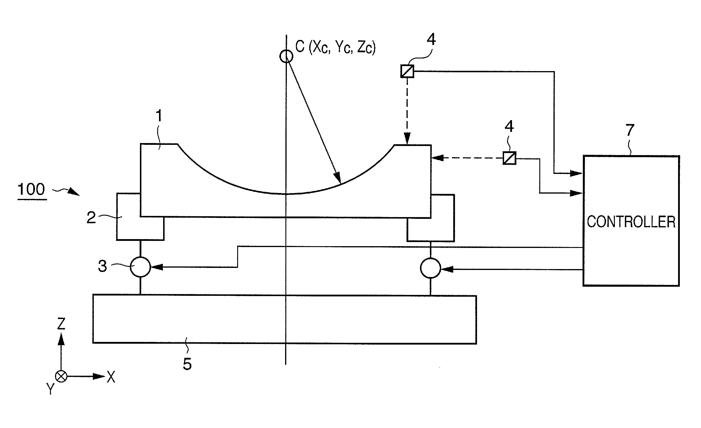
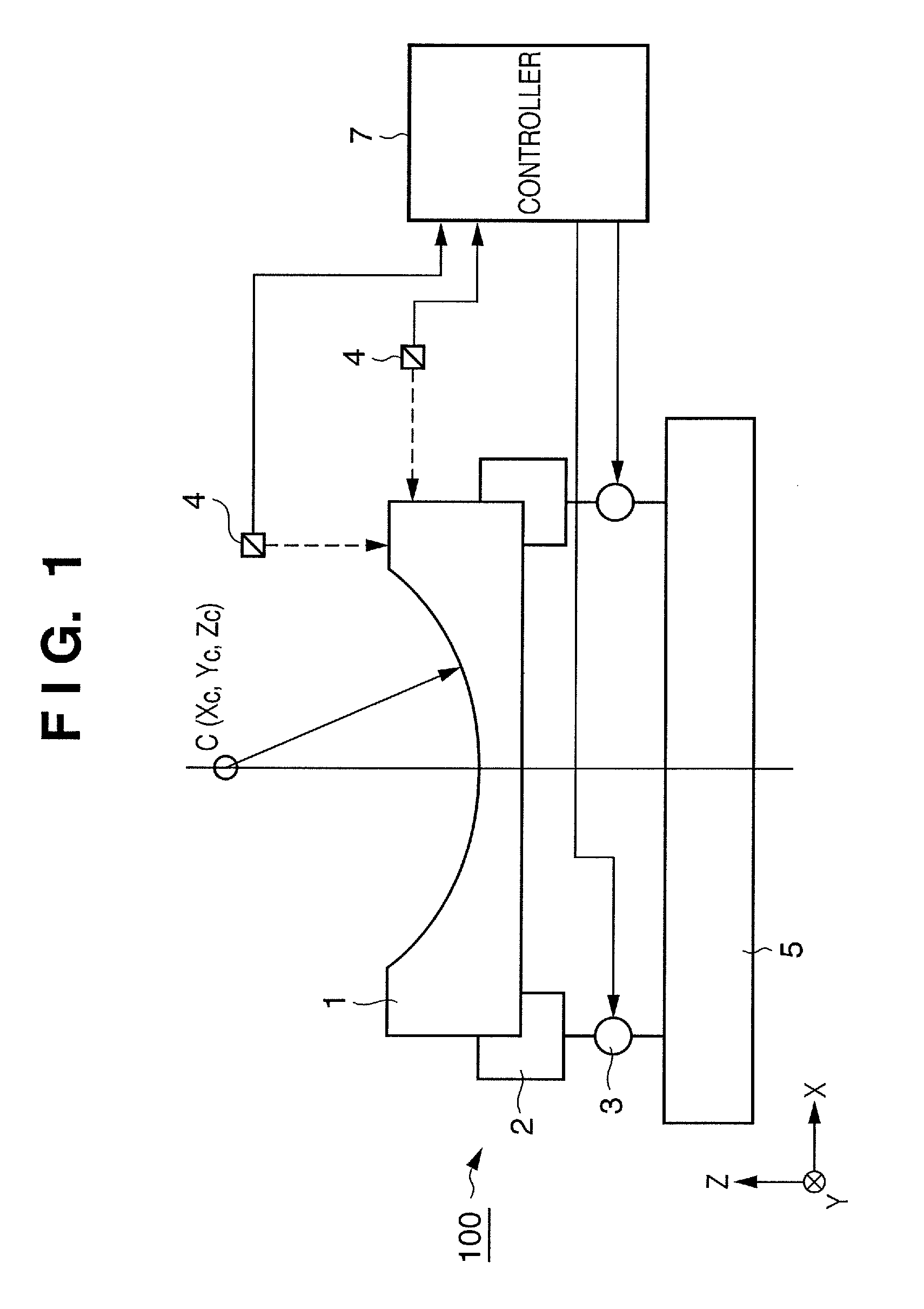
[0021]FIG. 1 is a diagram illustrating the structure of an optical element driving apparatus 100 according to this embodiment. As shown in FIG. 1, a curved-surface minor 1, which serves as an optical element, has a curved reflective surface. A typical example of a minor, used as the curved-surface minor 1, is a spherical minor having a reflective surface that defines a spherically concave surface. Let the direction of the optical axis be the Z axis, let two other directions forming a rectangular coordinate system with this axis be X and Y axes, and let the six-degrees-of-freedom of the curved-surface minor 1 be translations X, Y, Z and rotations θx, θy, θz, respectively, about these axes. Further, let C be the center of curvature of the curved-surface minor 1, and let C(Xc, Yc, Zc) represent the coordinates of the center of curvature. Further, let (ΔXc, ΔYc, ΔZc) represent a change in this position.
[0022]A minor support plate 2 supports the curved-surface minor 1. Three or more actu...
second embodiment
[0033]The X, Y, Z directions may be the three-degrees-of-freedom for driving an optical element driving apparatus for performing an adjustment in such a manner that the position C(Xc, Yc, Zc) of the center of curvature of the curved-surface mirror 1 takes on a desired value.
[0034]In this case, in a manner similar to the first embodiment, the controller 7 calculates fluctuation (ΔXm, ΔYm, ΔZm, Δθxm, Δθym, Δθzm) in position and attitude of the curved-surface minor through six-degrees-of-freedom, by a coordinate transformation, based upon the values measured by the position sensors 4 that measure six or more points on the curved-surface mirror 1. Next, the controller 7 calculates fluctuation (ΔXc, ΔYc, ΔZc) in the position C of the center of curvature of curved-surface mirror 1 by a coordinate transformation from the position and attitude of the curved-surface mirror 1, through six-degrees-of-freedom. It should be noted that the fluctuation in the position C of the center of curvature ...
third embodiment
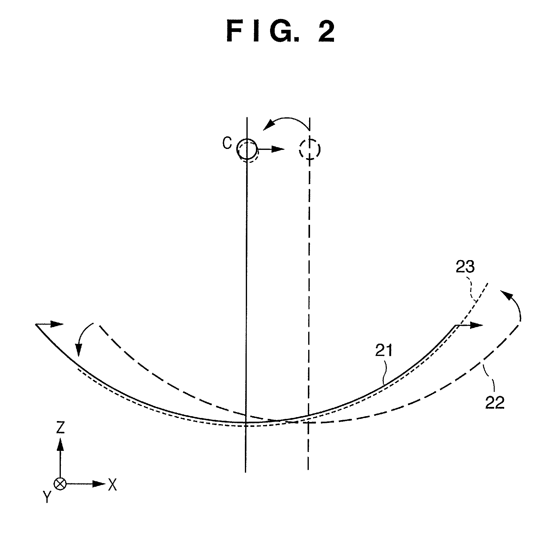
[0037]The Z, X directions and rotation θx about the X axis may be the three-degrees-of-freedom for driving an optical element driving apparatus for performing an adjusting in such a manner that the position C(Xc, Yc, Zc) of the center of curvature of the curved-surface minor 1 takes on a desired value.
[0038]Let (ΔXc, ΔYc, ΔZc) represent the positional deviation or other driving components of the center of curvature calculated by a coordinate transformation of the values measured by the position sensors 4. In this embodiment, the actuators 3 are driven and controlled so as to compensate for fluctuation of the position C of the center of curvature by an X translation ΔXc and rotation θx of ΔYc about the X axis. Further, the actuators 3 are driven and controlled so as to compensate for fluctuation of the position C of the center of curvature by a Z translation with regard to ΔZc.
PUM
 Abstract
Description
Claims
Application Information
 - R&D
- Intellectual Property
- Life Sciences
- Materials
- Tech Scout
- Unparalleled Data Quality
- Higher Quality Content
- 60% Fewer Hallucinations
Browse by: Latest US Patents, China's latest patents, Technical Efficacy Thesaurus, Application Domain, Technology Topic, Popular Technical Reports.
© 2025 PatSnap. All rights reserved.Legal|Privacy policy|Modern Slavery Act Transparency Statement|Sitemap|About US| Contact US: help@patsnap.com


