[0006]For greater ease of fitting or removing the fixed-point
pipe support and for simplifying the fixed-point
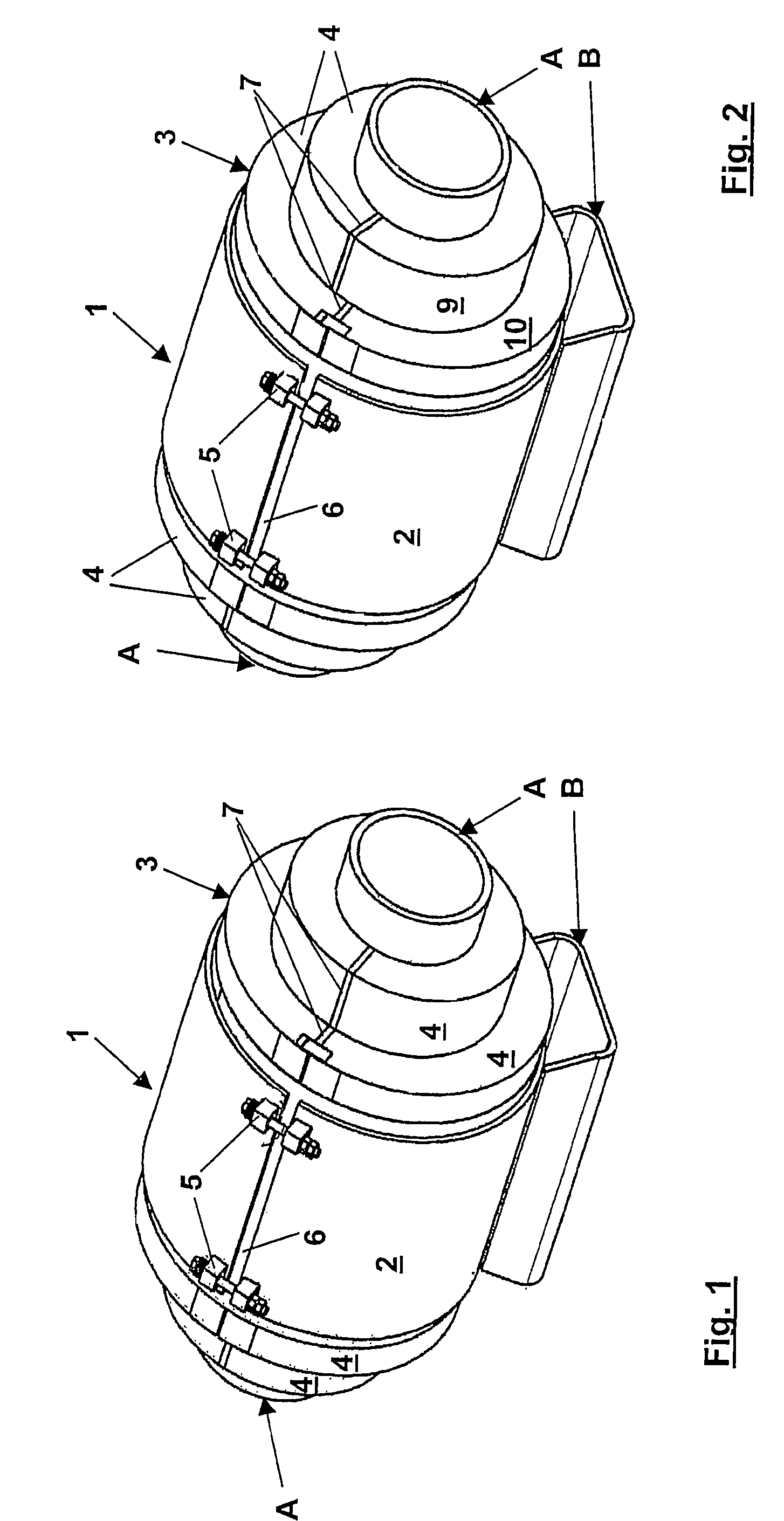
pipe support structure, the division in respect of shape should be so selected that the fixed-point
pipe support does not involve any
undercut configurations in relation to its fitting direction when being pushed on or released. For that purpose desirably the longitudinal axis of the fixed-point pipe support should lie in the division plane. A further simplification can be achieved if the
thermal insulation and the outer shell have a common division plane.
[0010]In order to ensure optimised connection to the insulating system of the pipeline to the fixed-point pipe support it is proposed that the thermal insulation in a development of the fixed-point pipe support projects in the axial direction beyond the outer shell. In that case the connection to the insulating system of the pipeline can be improved in that there is provided a preferably stepped configuration for the adjoining end faces to produce correspondingly stepped radial and axial joint portions in order in that way to prevent direct access for
moisture from the air. It can further be provided that the radial joint portions are filled with elastic sealing material.
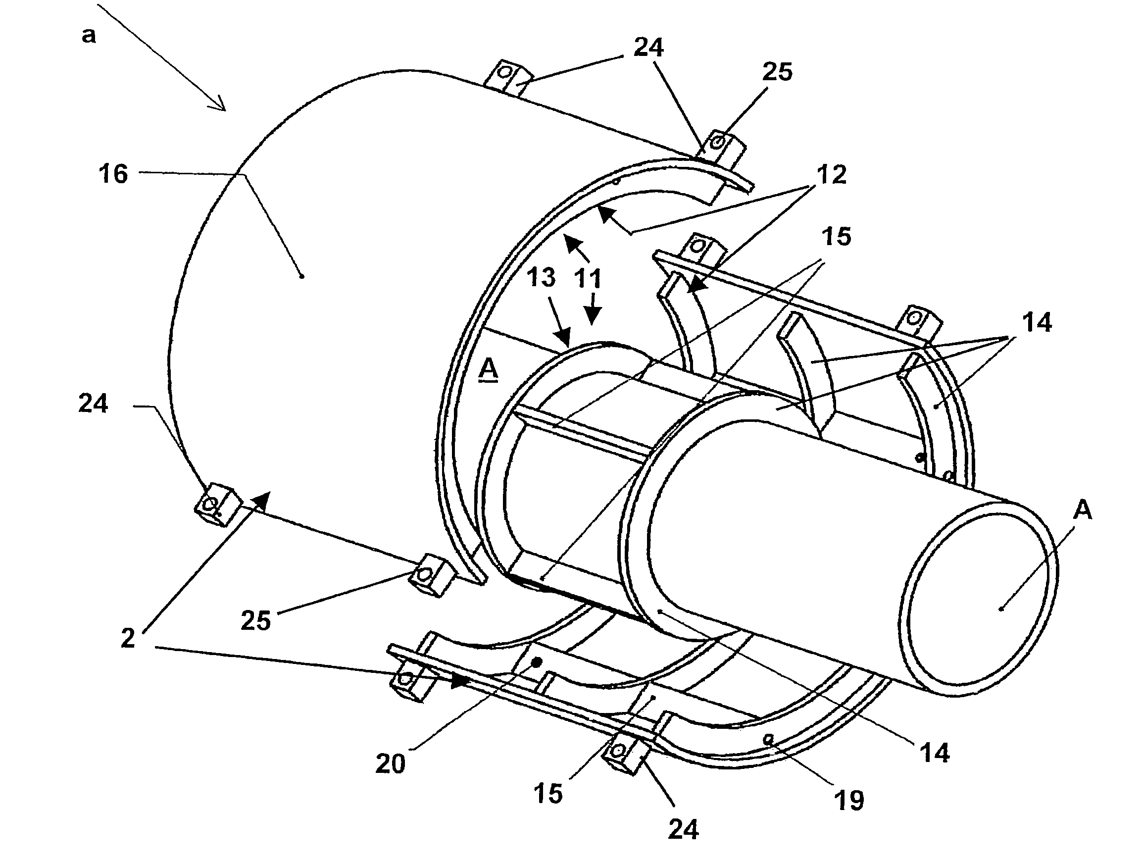
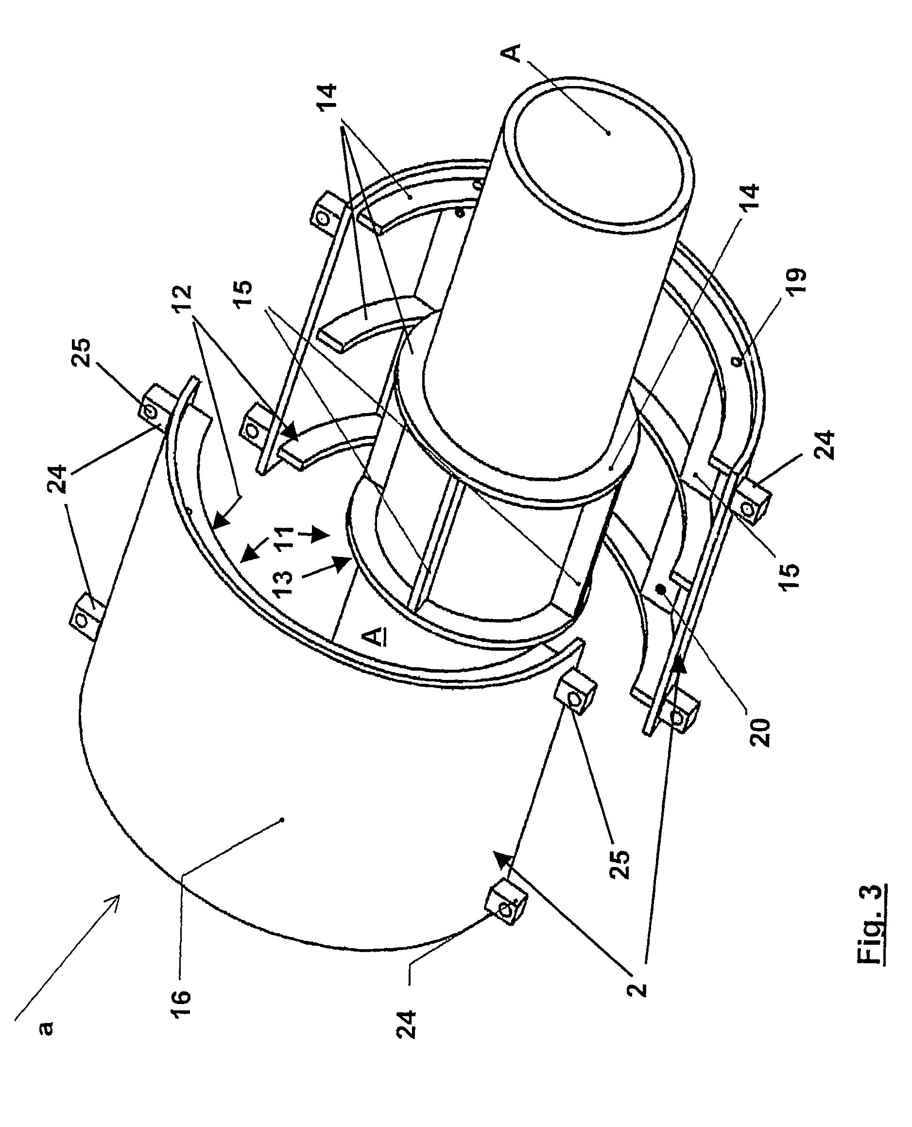
[0014]Preferably the receiving means each have at least one peripherally extending rib and at least one axially extending rib. Also the insulating system is provided with recesses which are adapted to the ribs and into which the ribs engage in the installed condition. Preferably the ribs engage completely and to such an extent that the ribs project into the recess to or close to the bottom of the receiving means. In a manner corresponding to the coaxial structure of the fixed-point pipe support, it is proposed that the ribs of the outer receiving means extend radially inwardly and the ribs of the inner receiving means extend radially outwardly. For reasons of stability of the receiving means and in order to pass the forces which occur to the insulating system under a material-compatible pressure, it is proposed that the receiving means respectively have at least two
peripheral ribs arranged at a mutual spacing and four axial ribs arranged distributed uniformly over the periphery, wherein the axial ribs preferably bear with their ends against a side face of the
peripheral ribs and are fixedly connected thereto. That increases the rigidity of the connection. The uniform arrangement of the four axial ribs distributed over the periphery implies a centre point angular spacing of 90°.
[0015]For more easily mounting the inner receiving means to the pipeline and in order to be able to introduce the outer receiving means into the divided outer shell, the two receiving means can be respectively divided into two receiving means halves, wherein their respective division plane extends perpendicularly to the cross-
sectional plane and contains the longitudinal axis of the receiving means. In that way the inner receiving means can be laterally fitted on to the pipe portion in question and assembled, in which case the ribs are preferably welded to the pipeline portion. Likewise the faces of the inner receiving means, which faces adjoin each other at the ends, can be welded together. The individual ribs of the inner receiving means however can also be welded individually on to the pipe, for
assembly thereof. In order to avoid corner or gusset welds which are undesirable from the point of view of a
welding procedure, in another variant the axial ribs can be fixed on the pipeline at a given end spacing in relation to the
peripheral ribs. In order to reduce the feed of heat into the pipeline by virtue of the operation of
welding on the ribs, it can also be provided that only at least peripheral and / or at least one radial rib are welded to the pipeline, in which case the unwelded ribs are welded to at least one rib which is welded to the pipeline, for the unwelded ribs to be held in position. Upon replacement of the insulating system or the thermal insulation and / or the outer shell, which for example is to be welded to another base, the inner receiving means itself can remain on the pipeline.
[0016]In order to avoid the formation of an
undercut configuration in respect of the thermal insulation, a respective one of the peripheral end faces, which are disposed in the division plane, of the receiving portions of the inner and / or outer receiving means can be formed by one of its axial ribs. By virtue of that arrangement the joint between the half-shells of the thermal insulation meets a respective axial rib radially inwardly and radially outwardly respectively, whereby stability is improved and direct access into the joint from the exterior is at least rendered more difficult.
[0019]The inner receiving means can preferably be made from high-quality steel. Because of the
advantage of the same material properties such as
thermal expansion,
welding characteristics and
corrosion characteristics, the inner receiving means should be made from the same material as the pipeline portion which is supported in the fixed-point pipe support. To reduce manufacturing costs, it is sufficient for the outer receiving means and the outer shell to be made from a non-alloyed steel, preferably a steel provided with a surface protection, in which case preferably both the receiving means and the outer shell should be of the same steel. In that respect pot galvanising is preferred as the surface protection.

