Apparatus for reducing drag on vehicles

Inactive Publication Date: 2011-01-04
BENTON CRAIG R
View PDF23 Cites 58 Cited by
  • Summary
  • Abstract
  • Description
  • Claims
  • Application Information

AI Technical Summary

Benefits of technology

[0012]It is an object of this invention to provide a wind

Problems solved by technology

When a vehicle moves, a low pressure area forms at the rear thereof which results in increased drag.
This increased drag forces the engine of the vehicle to work harder and thus, reduces m

Method used


Image

  • Apparatus for reducing drag on vehicles
  • Apparatus for reducing drag on vehicles
  • Apparatus for reducing drag on vehicles

Examples


Embodiment Construction

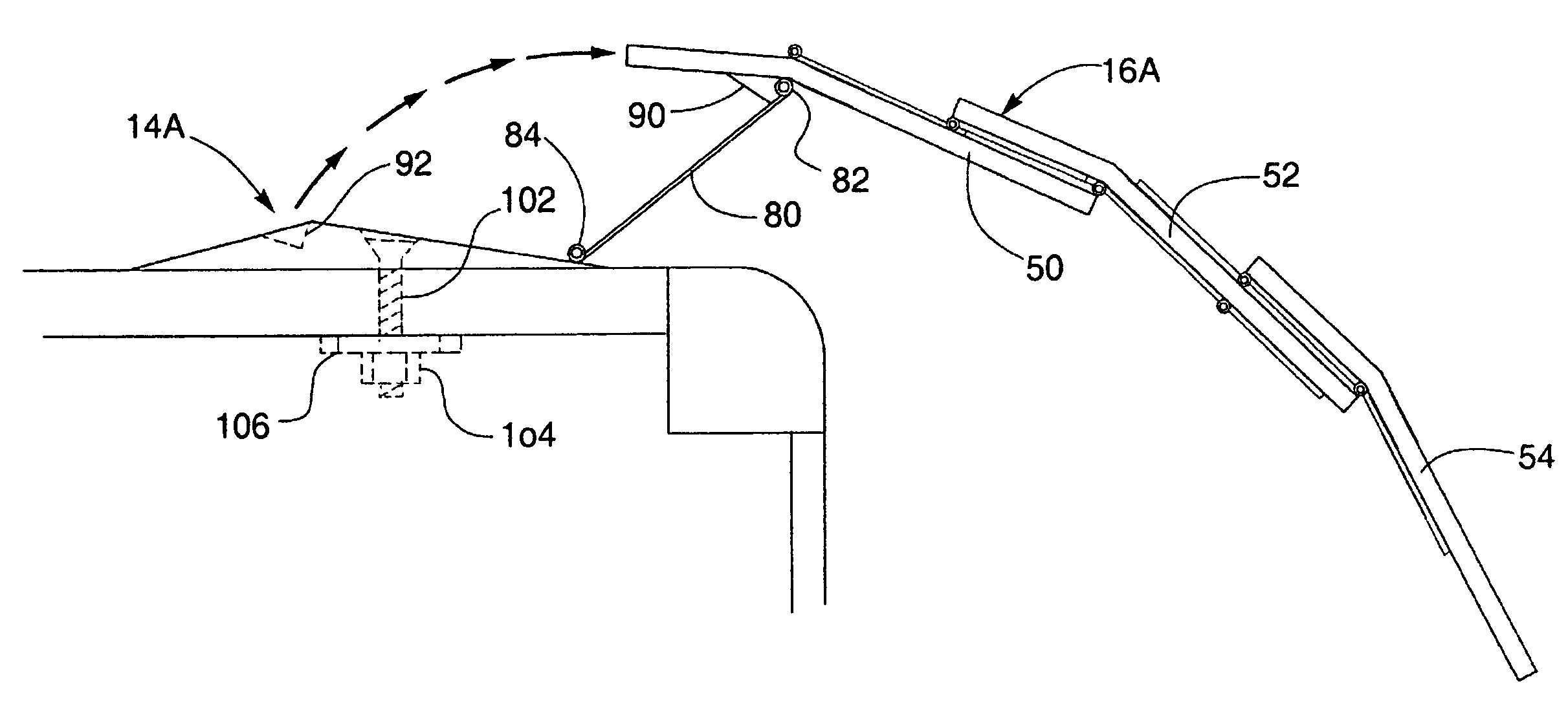
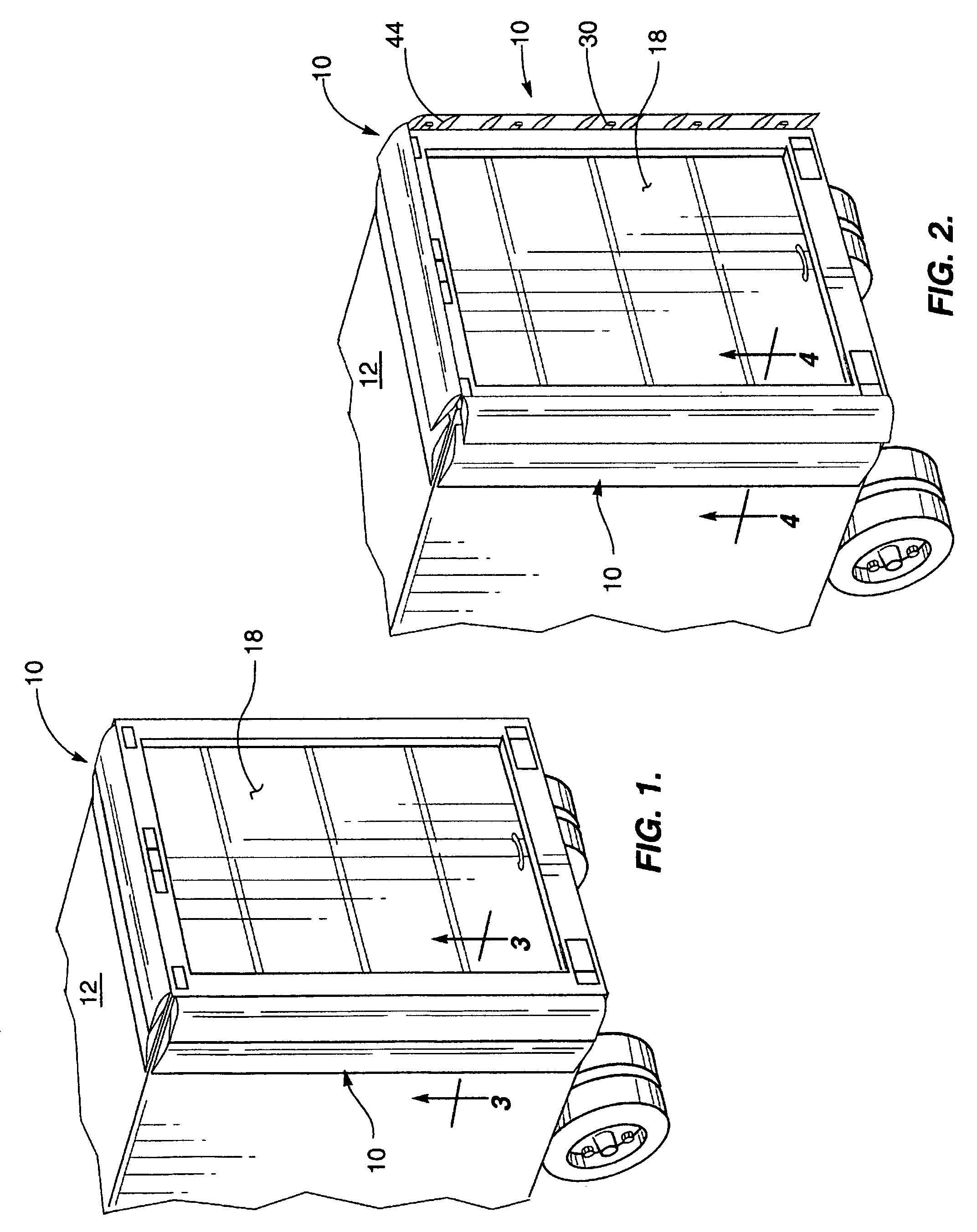
[0022]The invention is an apparatus 10 comprising a combination of movable diverters 16 and fixed diverters 14 mounted on the rear of vehicles 12 such as tractor-trailers, trucks and trains. When vehicle 12 is moving, a low pressure area 18 forms at the rear thereof which results in increased drag. Apparatus 10 diverts air flows to reduce or minimize low pressure area 18 to reduce drag. Each diverter, 14, 16 is mounted proximate to the rear of vehicle 12 along the top and sides thereof.

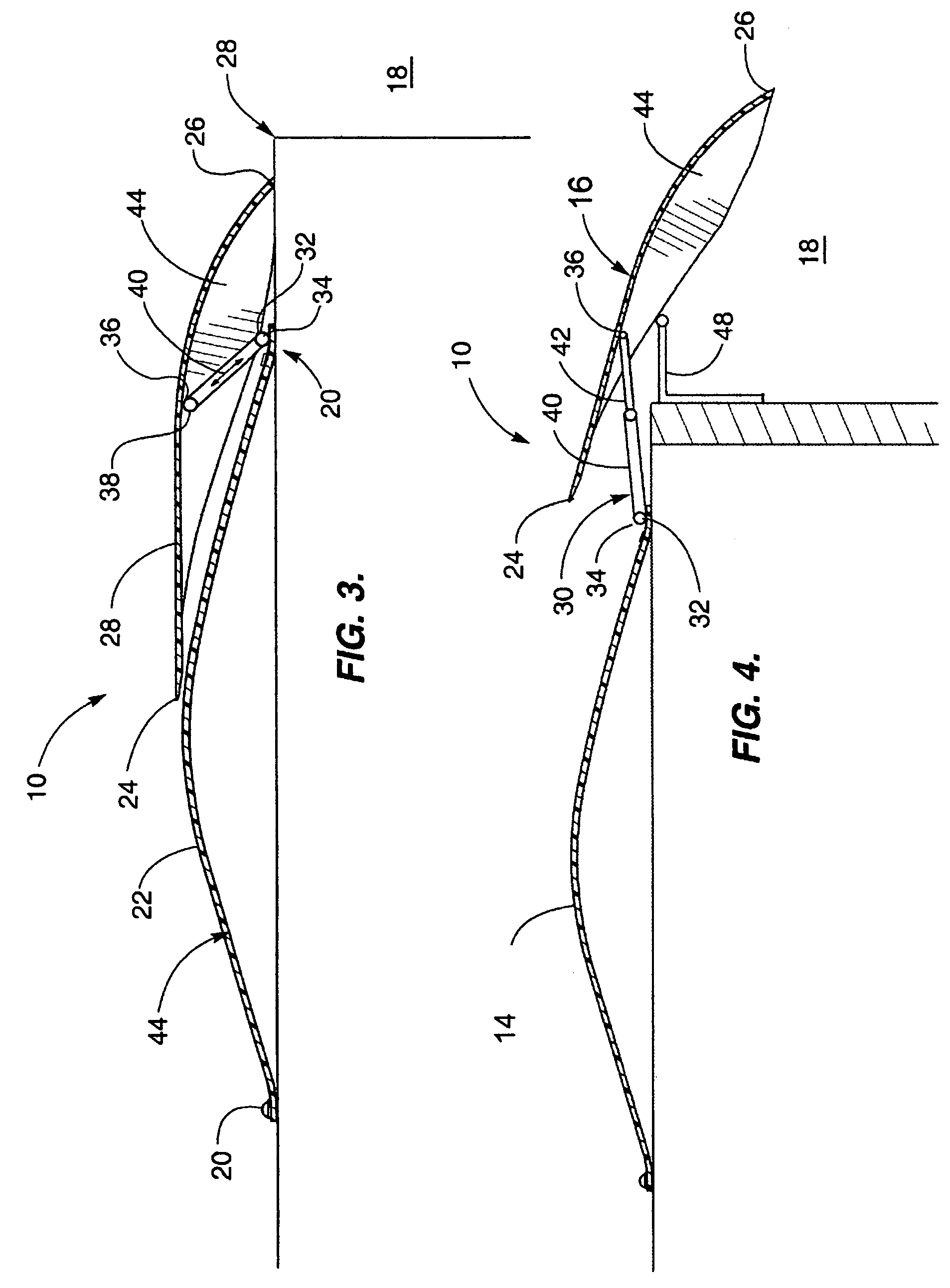
[0023]Fixed diverter 14 is positioned forward of movable diverter 16. As best seen in FIGS. 3 and 4, fixed diverter 14 has an aerodynamically shaped cross section which curves outwardly from a mount 20 attaching one end to vehicle 12, to a predetermined height 22 from which said fixed diverter curves inwardly to a second mount 20 which attaches the other end to vehicle 12.

[0024]Movable diverter 16 has a retracted position seen in FIG. 3 which has a forward end 24 which lays flat on fixed diverter 14 a...


PUM


Abstract

An apparatus for reducing the drag on a moving vehicle includes combinations of a movable diverter with a corresponding fixed diverter. Each combination is adapted to be mounted the rear of a vehicle with the fixed diverter positioned forward of the movable diverter. The movable diverter has a retracted position and an extended position and is biased to the retracted position. The movable diverter deploys to the extended position when moving above a predetermined velocity and returns to the retracted position when moving below the predetermined velocity. The movable diverter in the extended position having the rear end extending over the rear of a vehicle to direct air thereto.

Description

TECHNICAL FIELD[0001]This invention relates generally to the field of atmospheric drag reduction, and, more particularly, to an apparatus for reducing drag on vehicles such as trucks, trailers, trains and the like.BACKGROUND OF THE INVENTION[0002]When a vehicle moves, a low pressure area forms at the rear thereof which results in increased drag. This increased drag forces the engine of the vehicle to work harder and thus, reduces mileage. The increased drag is often aggravated by the shape of the vehicle. For example, the squared off end of a semi trailer causes far more drag than the rounded ends of a sports car.[0003]Thus, there is a need to reduce the increased drag caused by the low pressure area created behind a moving vehicle.[0004]There have been a number of drag reducing devices described in the art. For example, U.S. Pat. No. 5,280,990 entitled “Vehicle Drag Reduction System” which issued on Jan. 25, 1994 to Rinard describes fixed position mounted vanes to direct air to the...

Claims


Application Information

Patent Timeline
IPC IPC(8): B60J9/04
CPCB62D35/001
Inventor BENTON, CRAIG R.
Owner BENTON CRAIG R
Why Eureka
Try Eureka