Square membrane manifold system

a manifold system and membrane technology, applied in the direction of membranes, filtration separation, separation processes, etc., can solve the problems of high efficiency of systems, low efficiency of systems in the past, and high production, operation and maintenance costs, so as to reduce the amount of potting material, reduce the effect of cost and high strength

Active Publication Date: 2011-01-04
EVOQUA WATER TECH LLC
View PDF602 Cites 51 Cited by
  • Summary
  • Abstract
  • Description
  • Claims
  • Application Information

AI Technical Summary

Benefits of technology

[0006]The present invention seeks to overcome or at least ameliorate the problems of the prior art by providing a simple, effective manifolding and mounting system for submerged membranes modules.
[0015]In one form of the invention, the upper and lower potting heads are molded from a plastic material, typically injection-molded nylon, though it will be appreciated that other suitable molding materials could be used. The use of molded heads reduces the amount of potting material (e.g. polyurethane) required while also enabling intricate shapes to be formed in the potting heads for use with high strength mounting and connection arrangements. This results in cost reductions and more flexibility in mounting and connection arrangements.
[0016]According to a second aspect, the present invention provides a membrane module rack including a plurality of membrane modules according to the first aspect connected together by said headpieces. Preferably, the lower headers are also connected together by connection means. For preference, this connection means may be proved by interlocking formations provided on adjacent lower headers of the modules. For further preference, the formations are guides that slide into each other to interlock the adjacent headers and remove the need for extra loose parts.

Problems solved by technology

These systems are highly effective but are also expensive to produce, operate and maintain.
Simpler systems using membrane arrays freely mounted vertically in a tank and using suction applied to the fibre lumens to produce TMP have also been developed, however, these systems have been found in the past to be less effective than the pressurised systems.
Many of these systems require complex and expensive manifolding to provide the required delivery / removal of liquids and gas at various stages of the process.

Method used


Image

  • Square membrane manifold system
  • Square membrane manifold system
  • Square membrane manifold system

Examples


Embodiment Construction

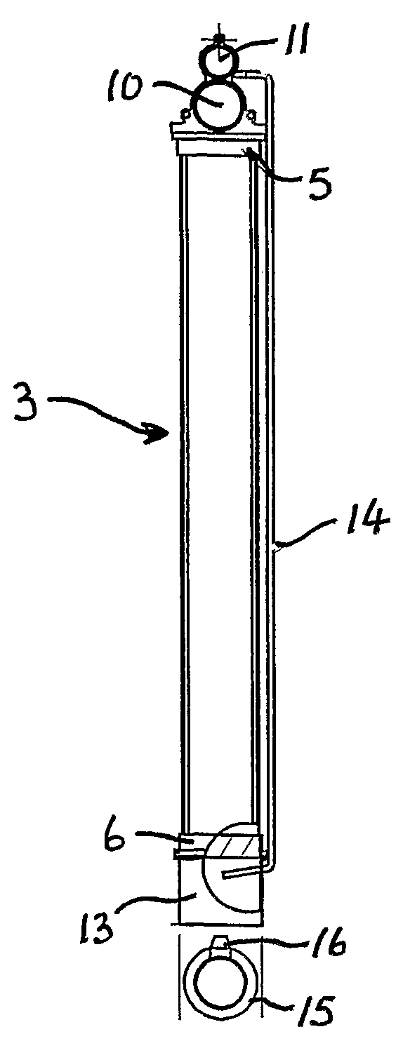
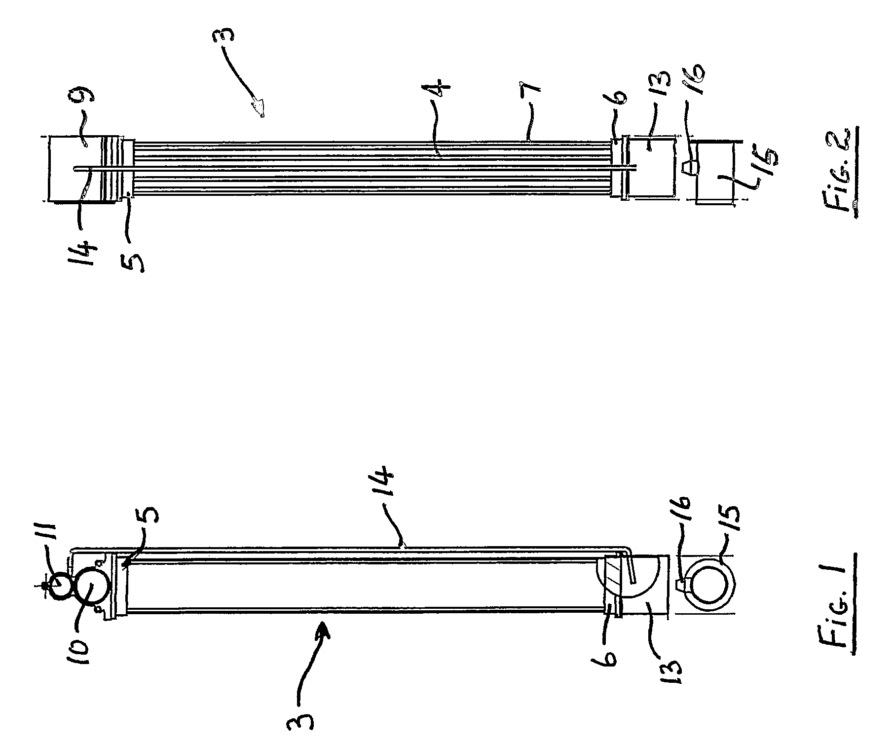
[0036]Referring to FIGS. 1 and 2, the membrane module 3, according to this embodiment, comprises a square-shaped in section array or bundle of hollow fibre membranes 4 extending longitudinally between upper and lower generally square shaped in section potting heads 5 and 6, respectively. While a square shaped module is shown and described it will be appreciated that other regular straight-sided shapes such as rectangular or triangular could also be employed. Such cross-sectional shapes enable closer packing of the modules.

[0037]A number of longitudinally extending spacer support rods 7 are positioned between the upper and lower potting heads 5 and 6. These rods are preferably potted into the upper and lower potting heads 5 and 6 during the potting process.

[0038]A screen or sleeve (not shown) at least partially surrounds the fibre bundles 4 along part of their length and serves to hold the fibres 8 in close proximity to each other, prevent excessive movement therebetween and prevent ...


PUM

PropertyMeasurementUnit
lengthaaaaaaaaaa
transmembrane pressureaaaaaaaaaa
transmembrane pressuresaaaaaaaaaa

Abstract

A membrane module (3) comprising a plurality of porous hollow membranes (8). The membranes (8) extend between and are fixed at each end in a header (5, 6). One header (6) has one or more of openings (12) formed therein. The openings (12) are in fluid communication with a source of gas and / or liquid (13, 14, 15). The other of the headers (5) is sealingly connected to and in fluid communication with a head-piece (9). The head-piece (9) is adapted to couple to an associated head-piece of a further module to form a rack of modules (17). A potting head (6) for use in mounting porous hollow membranes (8) is also disclosed comprising a preformed potting element (29). The potting element (29) includes one or more cavities (30) for receiving curate potting material which, in use, supports said membranes (8).

Description

TECHNICAL FIELD[0001]The present invention relates to submerged membrane filtration systems and more particularly to those types used in bioreactor processes.BACKGROUND ART[0002]A variety of membrane filtration systems are known and many of these use pressurised systems operating at high transmembrane pressures (TMP) to produce effective filtering and high filtrate flux. These systems are highly effective but are also expensive to produce, operate and maintain. Simpler systems using membrane arrays freely mounted vertically in a tank and using suction applied to the fibre lumens to produce TMP have also been developed, however, these systems have been found in the past to be less effective than the pressurised systems.[0003]Examples of such known systems are illustrated in U.S. Pat. No. 5,192,456 to Ishida et al, U.S. Pat. No. 5,248,424 to Cote et al and WO 97 / 06880 to Zenon Environmental Inc.[0004]Recent developments have used combinations of gas scouring and backwashing in non-pre...

Claims


Application Information

Patent Timeline
Patent Type & Authority Patents(United States)
IPC IPC(8): B01D65/02B01D35/20B01D29/00B01D37/00
CPCB01D61/18B01D63/021B01D63/022B01D63/024B01D63/04B01D63/043B01D65/00B01D65/08B01D61/20C02F1/444B01D2313/10B01D2313/12B01D2313/21B01D2315/06B01D2321/185
Inventor MCMAHON, ROBERT JAMESCOX, DAVID JOHNZHA, FUFANGPHELPS, ROGER WILLIAMJOHNSON, WARREN THOMASBARKHO, SARGON
Owner EVOQUA WATER TECH LLC
Why Eureka
Try Eureka