Ceramic metal halide lamp bi-modal power regulation control

a technology of ceramic metal halide and electric lamps, which is applied in the direction of lighting apparatus, instruments, light sources, etc., can solve the problems of limiting the market use of hidden lamps to professional applications, denying them to the general public, and not being able to interchange incandescent lamps with standard sockets

Inactive Publication Date: 2011-01-04
OSRAM SYLVANIA INC
View PDF15 Cites 28 Cited by
  • Summary
  • Abstract
  • Description
  • Claims
  • Application Information

AI Technical Summary

Benefits of technology

[0003]In one embodiment, a ballast includes a direct current (DC) converter, an oscillator, a switch, and a controller. The DC converter converts power from an alternating current (AC) power source to DC power and provides the DC power to the controller and the oscillator. The controller operates a switch to selectively alter an inductance of an inductor of the oscillator. Altering the inductance of the inductor causes the oscillator to operate at a different frequency such that the controller can switch the oscillator between a first frequency and a second frequency different from the first. The controller determines a duty cycle as a function of a voltage of the oscillator and a current of a power supply loop of the oscillator. The duty cycle is indicative of a percentage of a given time period during which the oscillator is to operate at the first frequency versus operating at the second frequency. The controller switches the oscillator between the first frequency and the second frequency as a function of the determined duty cycle.

Problems solved by technology

Therefore, HID lamps could not be used interchangeably with incandescent lamps in standard sockets.
This limits their market use to professional applications, and essentially denies them to the general public that could benefit from the technology.

Method used


Image

  • Ceramic metal halide lamp bi-modal power regulation control
  • Ceramic metal halide lamp bi-modal power regulation control
  • Ceramic metal halide lamp bi-modal power regulation control

Examples


Embodiment Construction

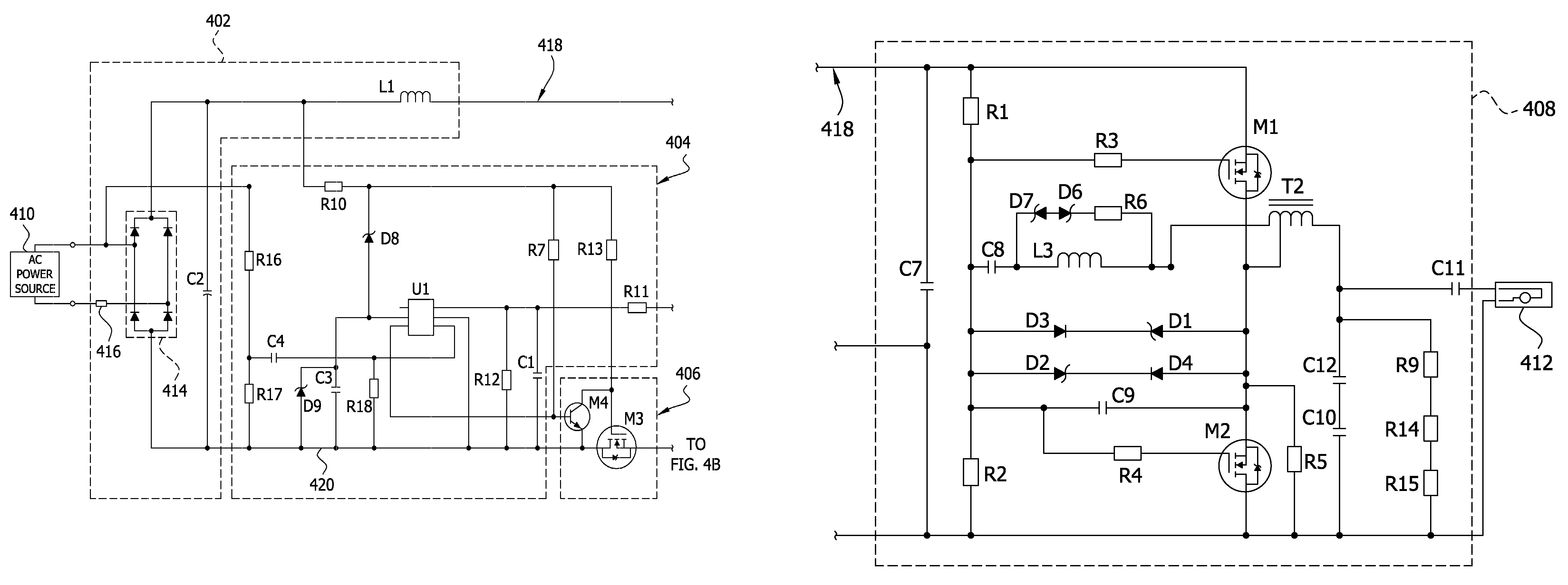
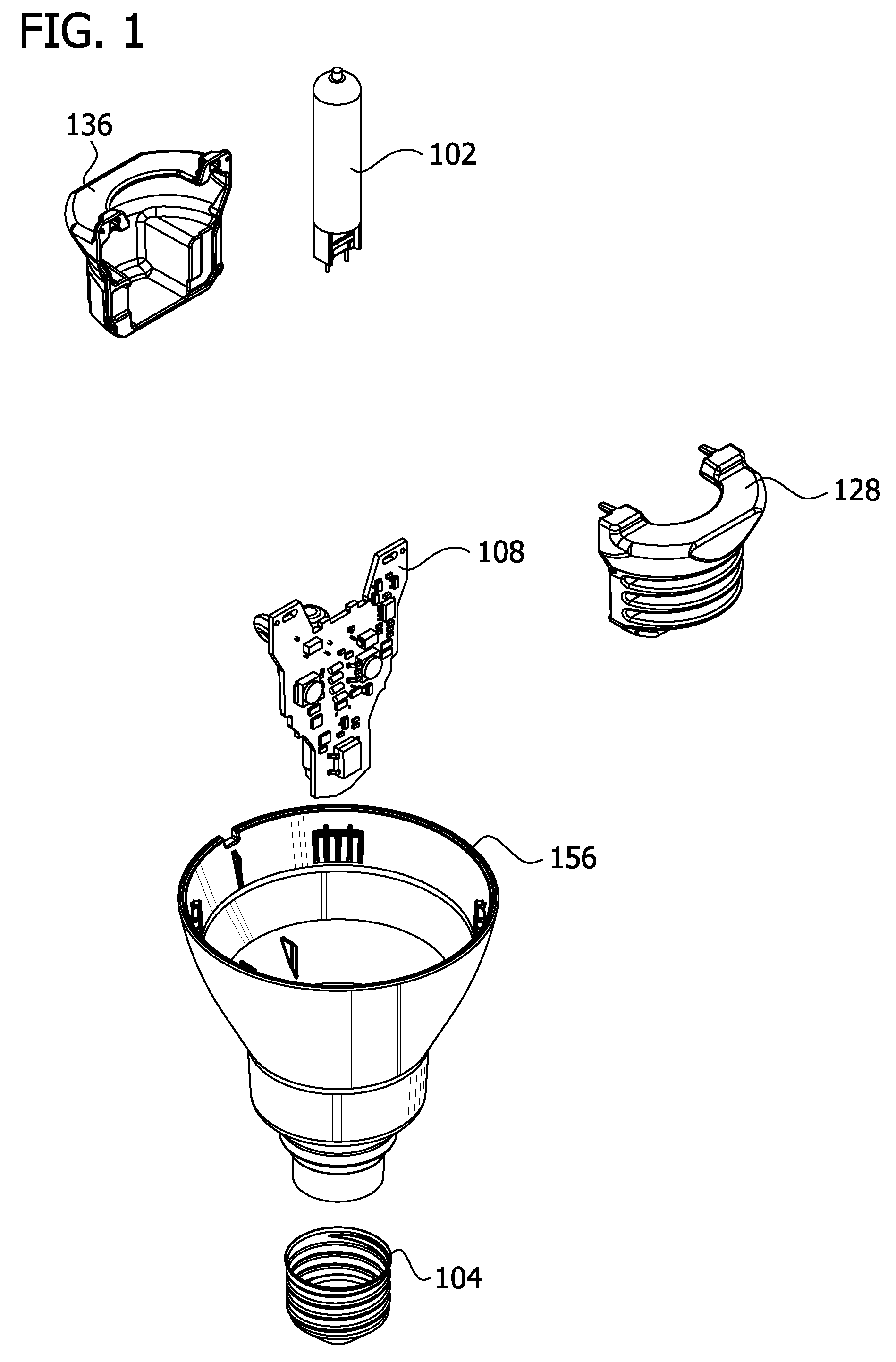
[0014]Referring to FIG. 1, a light source including an integrated ballast and HID lamp is shown in an exploded view. The HID lamp engages a circuit board 108 of the ballast and receives power from the circuit board 108 in operation. A first portion 136 and a second portion 128 of a heat sink thermally engage either side of the circuit board 108 of the ballast to dissipate heat generated by the ballast during operation of the lamp 102. An electrically non-conductive base 156 engages the heat sink (128 and 136), circuit board 108, a lamp 102, and a threaded connector 104 for engaging a socket (not shown). The threaded connector 104 connects the ballast to an alternating current (AC) power source (see FIGS. 4 and 5).

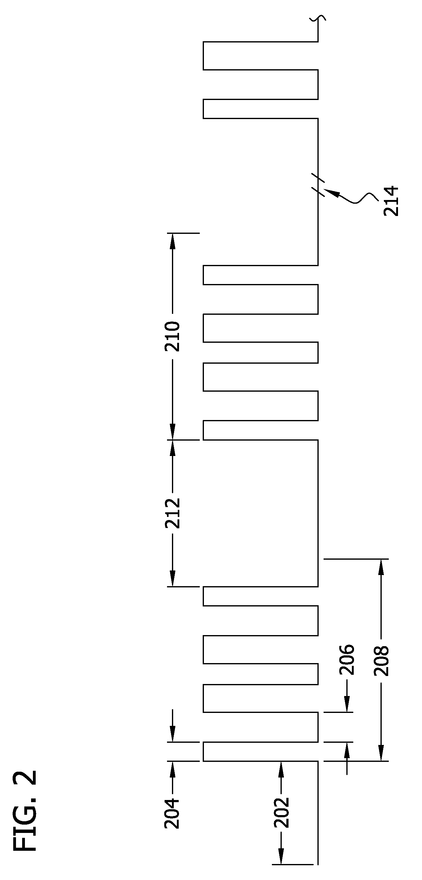
[0015]Referring to FIG. 2, a timing diagram for providing ignition pulses from an oscillator of the ballast to the lamp is shown. The diagram depicts the on and off switching of the oscillator of the ballast during ignition of the lamp, assuming that the lamp does not ignit...


PUM


Abstract

A high frequency ballast for a metal halide lamp comprises a controller, a switch, and an oscillator. The controller selectively enables and disables the oscillator via the switch to ignite the lamp. The switch selectively alters an inductance of the inductor to switch between a first frequency of the oscillator and a second frequency of the oscillator different than the first. The controller monitors a current of a power supply loop of the oscillator and a voltage of the oscillator and determines a duty cycle as a function of the monitored voltage and current. The duty cycle is indicative of the percentage of time that the oscillator is to operate at the first frequency versus the second frequency.

Description

FIELD OF THE INVENTION[0001]The present invention generally relates to a ballast for powering ceramic metal halide (ICMH) electric lamps. More particularly, the invention concerns selectively altering an inductance of an inductor in an oscillator of the ballast to control the power provided to the lamp.BACKGROUND OF THE INVENTION[0002]High intensity discharge (HID) lamps can be very efficient with lumen per watt factors of 100 or more. HID lamps can also provide excellent color rendering. Historically, HID lamps have been ignited by providing the lamp with a relatively long (5 milliseconds), high voltage (about 3 to 4 kilovolts peak to peak) ignition pulse. These relatively high power requirements necessitated the use of certain ballast circuit topologies and components having high power and voltage capacities. The required topologies and component capacities prevented miniaturization of ballasts and necessitated that starting and ballasting equipment be separate from the HID lamp. ...

Claims


Application Information

Patent Timeline
Patent Type & Authority Patents(United States)
IPC IPC(8): H05B37/02
CPCH05B41/2883
Inventor JOHNSEN, ANDREWWHITT, PHILLIP
Owner OSRAM SYLVANIA INC
Why Eureka
Try Eureka