Driving circuit with impedence calibration and pre-emphasis functionalities

a technology of impedence and function, applied in the direction of electronic switching, reliability increasing modifications, electric devices, etc., can solve the problems of increasing circuitry, doubling the overall power consumption, and inevitably entail higher fabrication costs, and achieve the effect of less power consumption

Inactive Publication Date: 2011-01-04
HIMAX IMAGING LIMITED
View PDF18 Cites 18 Cited by
  • Summary
  • Abstract
  • Description
  • Claims
  • Application Information

AI Technical Summary

Benefits of technology

[0010]In light of this, an exemplary embodiment of the present invention provides a novel driving circuit (e.g., a novel LDVS driver) capable of a

Problems solved by technology

The conventional pre-emphasis functionality, however, usually requires additional circuitry and will inevitably entail higher fabrication costs.
In addition, as the data rate rises up to giga bits per second (Gbps) and the cable length becomes longer, the impedance matching issue becomes crucial to prevent signal reflection at both the transmitter and receiver side.
Unfortun

Method used


Image

  • Driving circuit with impedence calibration and pre-emphasis functionalities
  • Driving circuit with impedence calibration and pre-emphasis functionalities
  • Driving circuit with impedence calibration and pre-emphasis functionalities

Examples


Embodiment Construction

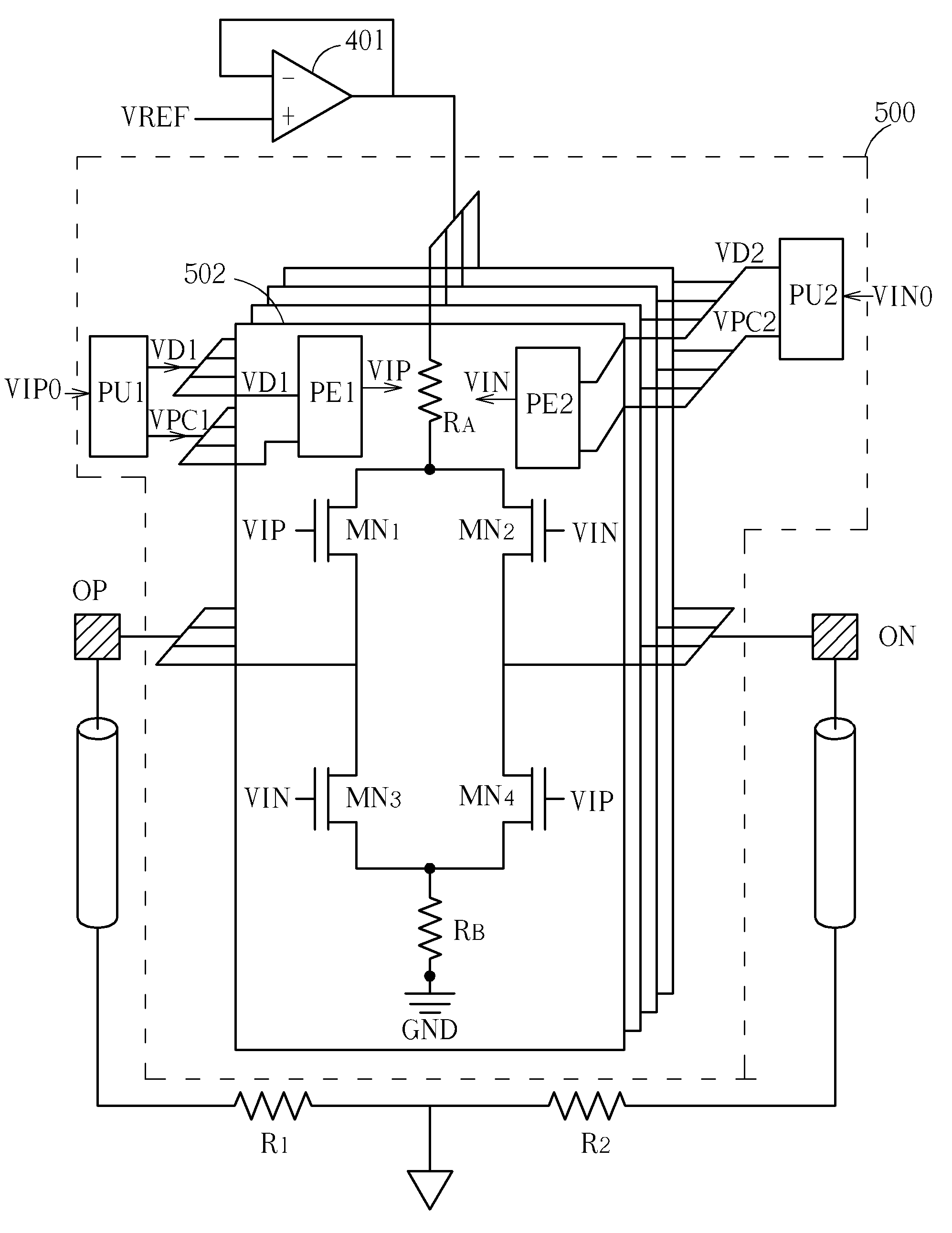
[0025]Please refer to FIG. 4, which shows a driving circuit (e.g., an LDVS driver) according to an embodiment of the present invention. The exemplary driving circuit 400 includes, but is not limited to, a first processing unit PU1, a second processing unit PU2 and a plurality of driving units. In FIG. 4, only a driving unit 402 is illustrated with detail here for simplicity since each driving unit is designed to have the same circuit structure. The driving unit 402 includes a first pre-emphasis unit PE1, a second pre-emphasis unit PE2, a first bias component RA, a second bias component RB, a first metal-oxide-semiconductor (MOS) transistor MN1, a second MOS transistor MN2, a third MOS transistor MN3, and a fourth MOS transistor MN4, where the first, second, third, and fourth MOS transistors MN1-MN4 have the same conductive type. By way of example, rather than limitation, the first and second bias components RA and RB are implemented using resistors, and the first, second, third, and...


PUM


Abstract

A driving circuit includes at least a driving unit, a first processing unit and a second processing unit. The driving circuit includes a first bias component, a second bias component, a first pre-emphasis unit, a second pre-emphasis unit, and a transmitter unit. The first bias component has a first node coupled to a first reference voltage and a second node for outputting a first bias current. The second bias component has a first node for draining a second bias current and a second node coupled to a second reference voltage different from the first reference voltage.

Description

CROSS REFERENCE TO RELATED APPLICATIONS[0001]This continuation-in-part application claims the benefit of co-pending U.S. application Ser. No. 12 / 628,226, filed on Dec. 1, 2009, and incorporated herein by reference.BACKGROUND OF THE INVENTION[0002]1. Field of the Invention[0003]The present invention relates to a driver, and more particularly, to a low-power high-speed driving circuit with auto-calibration and pre-emphasis functionalities.[0004]2. Description of the Prior Art[0005]As the resolution of image sensors or displays increases, the data rate becomes very high. As a result, a requirement for a high-speed driver with superior performance grows. For all kinds of high-speed drivers, a low voltage differential signal (LVDS) technique is frequently utilized due to a lower electromagnetic interference (EMI), lower power consumption and a better signal integrity than that of a conventional CMOS full swing driver. Please refer to FIG. 1, which is a diagram of a conventional LVDS driv...

Claims


Application Information

Patent Timeline
IPC IPC(8): H03K19/094H03K19/0175
CPCH03K19/018564H03K19/018585
Inventor LIU, CHIH-MINYIN, PING-HUNGHUANG, KUO-CHAN
Owner HIMAX IMAGING LIMITED
Why Eureka
Try Eureka