Fingerprint sensor element

a technology of fingerprint and sensor element, which is applied in the field of fingerprint sensor element, can solve the problems of parasitic capacitors, large bulky and sensitive to dirt, and disturbing the measurement, and achieves the effect of efficient use of available layers and elimination of parasitic capacitors

Active Publication Date: 2011-01-04
FINGERPRINT CARDS ANACATUM IP AB
View PDF28 Cites 159 Cited by
  • Summary
  • Abstract
  • Description
  • Claims
  • Application Information

AI Technical Summary

Benefits of technology

[0014]It is therefore an object of the present invention to provide a fingerprint sensor element that more efficiently eliminates the parasitic capacitors and enables a more efficient use of the available layers.
[0022]A high gain and a low SNR allow the use of a relatively thick protective coating, leading to an enhanced ESD protection.
[0023]The lateral parasitic capacitance effects are reduced, resulting in an increased resolution.
[0024]The layers of the fingerprint structure are more efficiently used.
[0025]The interference noise is reduced since the parasitic capacitances are reduced.
[0027]A relatively large distance may be present between the layers in order to further minimize the total input capacitance and thus the amplifier noise.

Problems solved by technology

However, these optical reading sensor elements are quite expensive, bulky and sensitive to dirt.
A problem for all capacitive fingerprint sensors of today is the presence of parasitic capacitors.
Since this parasitic capacitor can be much larger then the capacitance to the finger, it can disturb the measurement.
Having a large capacitor at the input of a charge amplifier, as is the case in this article, is, however, disadvantageous concerning noise performance of the sensor element.
The fact that a large parasitic capacitor at the input of a charge amplifier is disadvantageous concerning noise performance, is a previously known fact.
Furthermore, the article discloses sensor electrodes which are not kept at the same potential, which makes the measurement of the capacitance between the finger and each sensor electrode dependant on lateral parasitic capacitances, which will vary with the current local skin condition, leading to a deteriorated fingerprint image.
This results in an unreliable measurement with a reduced image resolution.

Method used


Image

  • Fingerprint sensor element
  • Fingerprint sensor element
  • Fingerprint sensor element

Examples


second embodiment

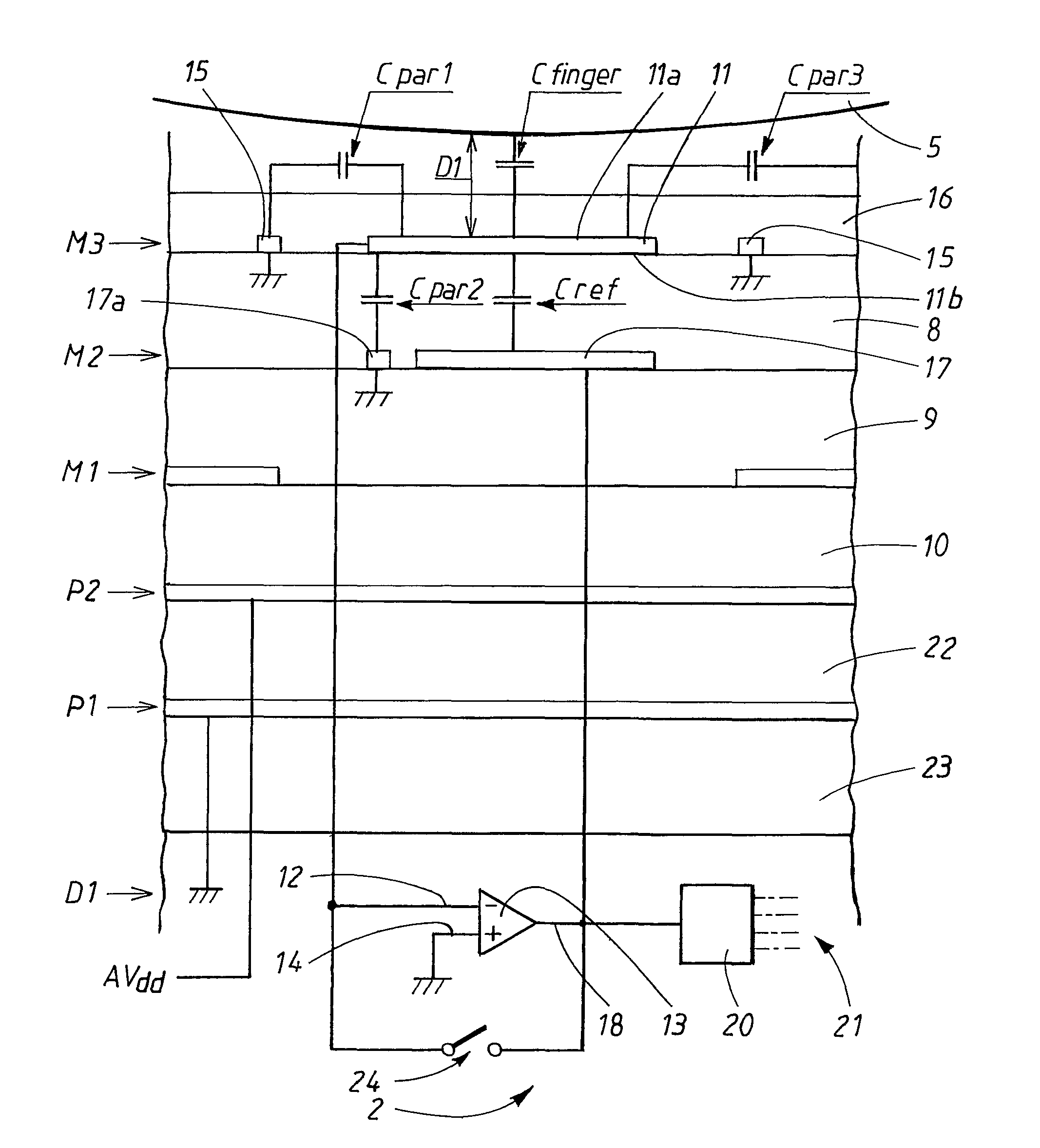
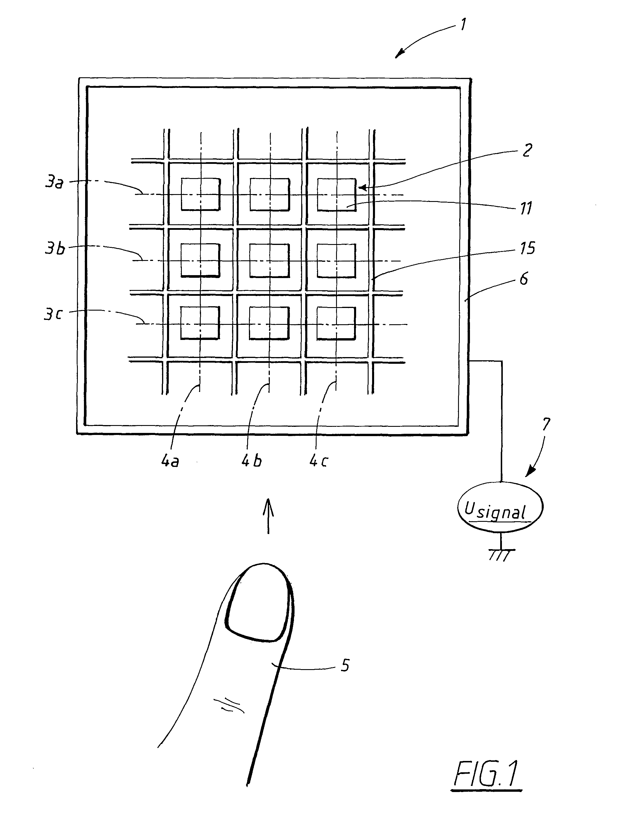
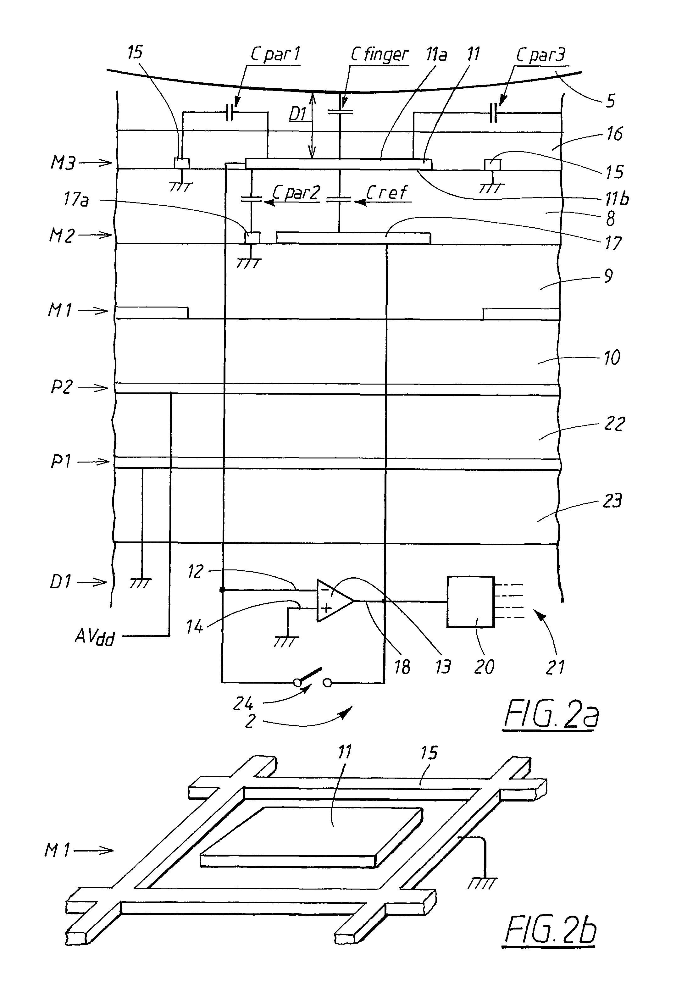
[0072]In the invention, shown in FIG. 6, the control unit 20 of the fingerprint sensor 1 is adapted for injecting a signal Usignal to the finger 5, or sensing a signal from the finger 5, via the sensor electrodes 11. The sensor electrodes 11 alternate, either injecting a signal Usignal or receiving an injected signal via the finger 5. For each sensor element 2, the control unit 20 controls a signal switch 32a that opens and closes a connection from the signal source 7 generating the signal Usignal that is to be injected into the finger 5. Therefore, at a specific moment, some of the sensor electrodes 11 of the fingerprint sensor 1 function as sensor elements while the rest of the sensor electrodes function as means for injecting the signal Usignal to the finger 5. At another moment some of the sensor electrodes 11 may have switched between these functions. In this embodiment, the frame 6 surrounding the fingerprint sensor elements 2 is only needed for ESD protection.

[0073]With regar...

third embodiment

[0078]In FIG. 7, according to the present invention, a fingerprint structure according to the above is used in a different way. The negative input terminal 12 of a charge amplifier is here connected to a sensor electrode 11 in the first conductive layer M3. The fifth layer that is constituted by an electrically conductive layer P1 has a lower electrode 33 formed that is connected to the output 18 of the charge amplifier 13, increasing a distance D2 between the electrodes of the feedback capacitor Cref that now is formed between the sensor 11 electrode and the lower electrode 33, since there are no interfering structures between them, only the intermediate insulting dielectric layers 8, 9, 10, 22. For this purpose, apertures are made in the intermediate conducting layers M1, M2, P2. This increase of D2 decreases the total capacitance at the negative input terminal 12 of the charge amplifier 13, which in turn results in that the total noise of the circuit also decreases, since, as kno...


PUM


Abstract

The present invention relates to a fingerprint sensor element, comprising a sensor electrode formed in an upper conducting layer, a lower electrode formed in a lower conducting layer and at least one insulating layer between the upper conducting layer and the lower conducting layer. It further comprises a charge amplifier having a negative and a positive input terminal and an output terminal. An upper side of the fingerprint sensor electrode is arranged for facing a finger and a lower side is arranged for facing the lower electrode, and the fingerprint sensor electrode and the lower electrode are arranged in such a way that a capacitance is formed between them. The sensor electrode is arranged for being connected to the negative input terminal of the charge amplifier, and the lower electrode is arranged for being connected to the output terminal of the charge amplifier.

Description

RELATED APPLICATIONS[0001]This application is a nationalization under 35 U.S.C. 371 of PCT / SE2004 / 000985, filed Jun. 18, 2004 and published as WO 2005 / 124659 A1, on Dec. 29, 2005, which application and publication are incorporated herein by reference and made a part hereof.TECHNICAL FIELD[0002]The present invention relates to a fingerprint sensor element comprising a fingerprint sensor electrode formed in an upper conducting layer, a lower electrode formed in a lower conducting layer, at least one insulating layer between the upper conducting layer and the lower conducting layer, a charge amplifier having a negative and a positive input terminal and an output terminal, where an upper side of the fingerprint sensor electrode is arranged for facing a finger and a lower side of the fingerprint sensor electrode is arranged for facing the lower electrode, and where the fingerprint sensor electrode and the lower electrode are arranged in such a way that a capacitance is formed between the...

Claims


Application Information

Patent Timeline
Patent Type & Authority Patents(United States)
IPC IPC(8): G06K9/00
CPCG06K9/0002G06V40/1306
Inventor RIEDIJK, FRANK ROBERTHAMMERSBERG, JOHAN
Owner FINGERPRINT CARDS ANACATUM IP AB
Why Eureka
Try Eureka