Modular universal holding fixture

a technology of holding fixture and module, applied in the field of aviation, can solve the problems of inconvenient conventional machining techniques for metal parts, inhibiting the future growth of part families, and complex operation of linear actuator types, and achieve the effect of less costly tooling

Active Publication Date: 2011-01-11
THE BOEING CO
View PDF17 Cites 27 Cited by
  • Summary
  • Abstract
  • Description
  • Claims
  • Application Information

AI Technical Summary

Benefits of technology

[0004]Systems and methods are disclosed herein to provide a modular universal holding fixture capable of supporting a workpiece during a manufacturing operation; providing high-precision manufacturing operations using less costly tooling; and accommodating workpieces exhibiting a wide range of contours, geometries, and configurations.

Problems solved by technology

In general, a composite material is typified by a structure of very strong fibers embedded in a softer matrix, for which the conventional machining techniques employed on metal parts may not be suitable.
In general, current holding fixtures provide a fixed machine bed pattern having a limited number of tooling mounting locations available to support a limited number of tooling devices.
In addition, a fixed machine bed pattern does not accommodate workpieces exhibiting a wider range of contours, geometries, and configurations, thereby inhibiting the future growth of part families.
Understandably, this type of linear actuator may be more expensive and complex to operate.
In some cases, self-positioning by individual tooling may provide less accurate workpiece positioning due to the variability of errors among the array of tooling apparatus, and additional quality control equipment or processes may be needed.
Therefore, current universal holding fixtures, as well as implementations attempting to address the aforementioned limitations, tend to be costly, complex, or both.

Method used


Image

  • Modular universal holding fixture
  • Modular universal holding fixture
  • Modular universal holding fixture

Examples


Embodiment Construction

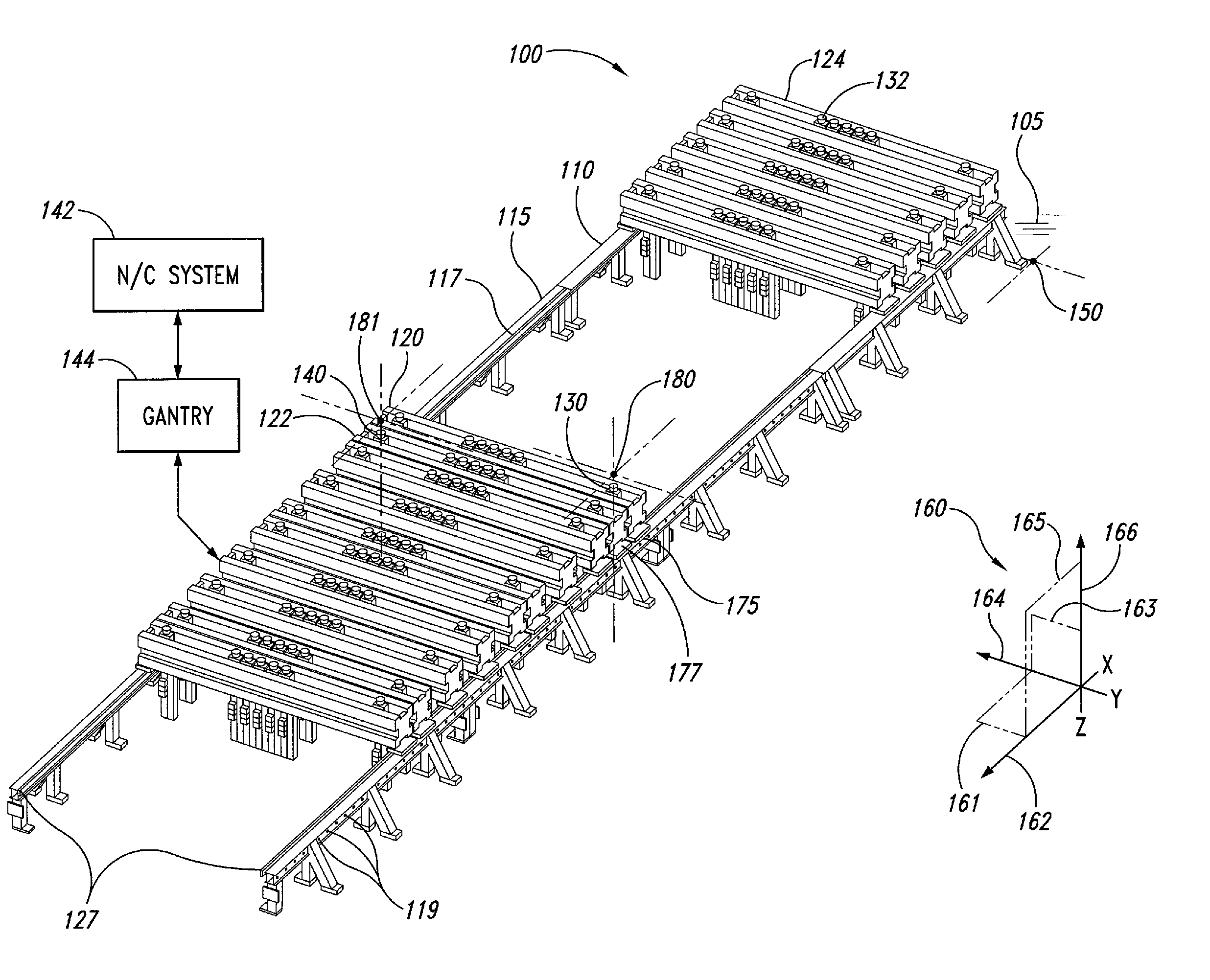
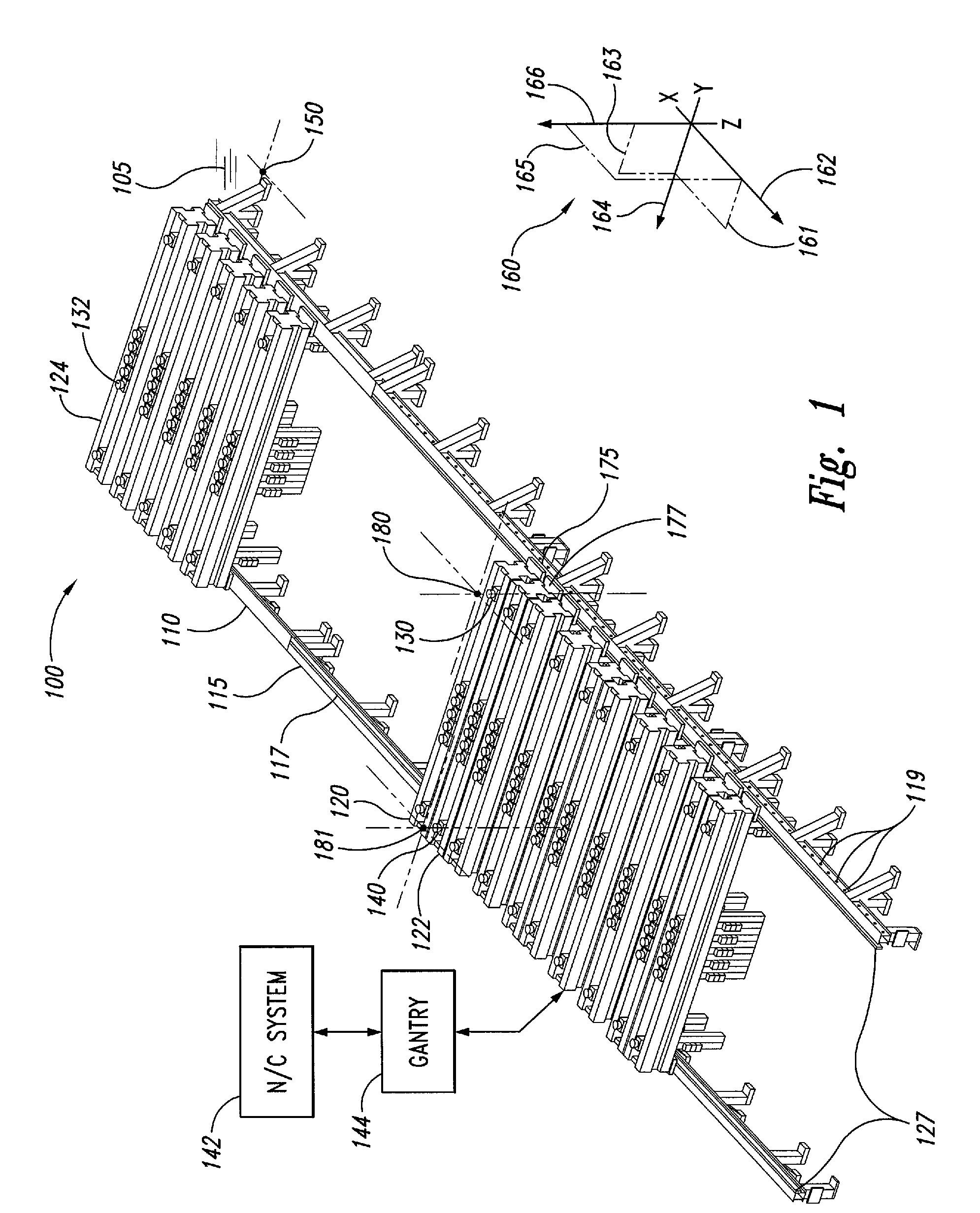
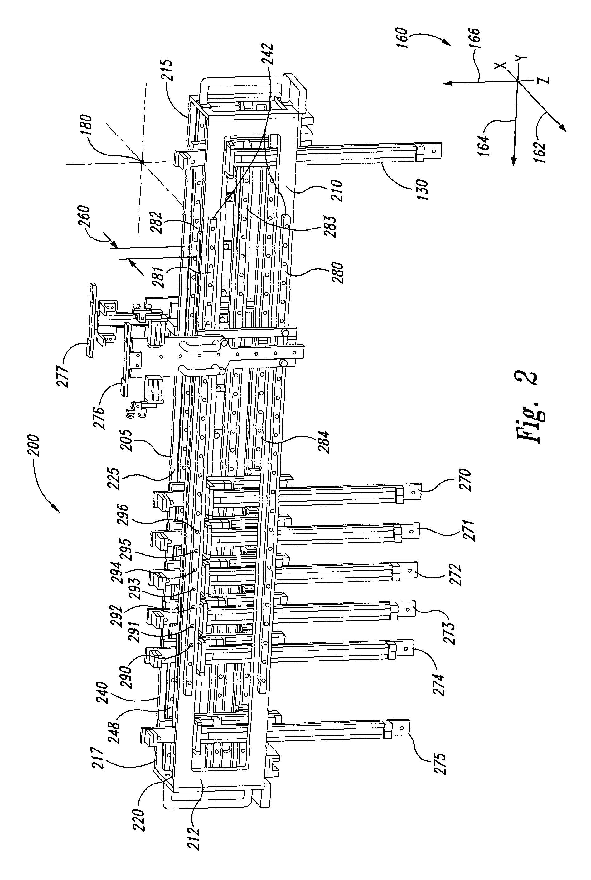
[0019]The present disclosure describes embodiments of a modular universal holding fixture and corresponding methods, capable of accommodating a wide range of workpiece contours, geometries, sizes, and configurations. The universal holding fixture herein may be configured in one or more embodiments to hold a workpiece in a definable spatial relationship relative to a known fiducial location, or “home,” within a corresponding spatial reference system. A fiducial location generally describes a known reference location that may be used by a human operator or a machine to identify boundary conditions within a common spatial reference system and to identify selected locations in the reference system with uniformly high precision. By way of definition, registration is the process of establishing correspondences between a local frame of reference and a defined fiducial location; a registration position is an identified location for which such a local frame of reference has been established....


PUM

PropertyMeasurementUnit
lengthaaaaaaaaaa
widthaaaaaaaaaa
structureaaaaaaaaaa

Abstract

A modular universal holding fixture and corresponding methods, accommodating a wide range of workpiece contours, geometries, sizes, and configurations. The fixture may include a fiducial base, a registration frame, and a bridge module. Fixable to a fiducial (reference) location, the fiducial base may be attached in alignment to the registration frame. The bridge module may have a central cavity and guide tracks on top, exterior, and interior support surfaces. The bridge module transversely engages the registration frame for longitudinal movement to a registration position, and supports a tooling for transverse movement. The bridge module may repositionably constrain the tooling at an indexed position. The bridge module may be configured to engage multiple types of tooling and additional tooling headers, supports, and side actuators. A tooling may be passive linear actuators positioned by a N / C operated gantry engaged with the registration frame.

Description

TECHNICAL FIELD[0001]This invention generally pertains to the field of aviation, in general, and more particularly, to a holding fixture used to hold a workpiece during aircraft manufacturing.BACKGROUND[0002]In the production of contoured panels and parts utilized in aircraft or other large structures, it is desirable to securely hold a workpiece in order to perform precision machining or finishing operations. These operations may include, for example, cutting, drilling, trimming, and smoothing. Particularly in the aerospace industry, strong, lightweight workpieces made of composite materials are employed for an increasingly wider range and geometry of aircraft parts. In general, a composite material is typified by a structure of very strong fibers embedded in a softer matrix, for which the conventional machining techniques employed on metal parts may not be suitable. Instead, many machining or smoothing operations on composite workpieces employ high-pressure water jets guided by a ...

Claims


Application Information

Patent Timeline
Patent Type & Authority Patents(United States)
IPC IPC(8): B25B1/20
CPCB23Q1/035B23Q1/037B23Q2230/002Y10T29/5191Y10S269/91Y10T409/307728Y10S269/904
Inventor MCALLISTER, STEVEN J.
Owner THE BOEING CO
Why Eureka
Try Eureka