Venous filters

a filter and vein wall technology, applied in the field of filters, can solve the problems of inability to remove the filter, the vessel wall is gravely injured, and the complications of temporary filters are inacceptabl

Active Publication Date: 2011-01-11
UNITED STATES OF AMERICA
View PDF7 Cites 27 Cited by
  • Summary
  • Abstract
  • Description
  • Claims
  • Application Information

AI Technical Summary

Problems solved by technology

However, most filters are generally retrievable only up to about 14 days from deployment, because of fibrotic wall reactions and endothelialization that starts on the third week following deployment.
Therefore, any manipulation of these implanted struts after the second week may result in grave injury of the vessel wall with subsequent complications including: life threatening bleeding, dissection of vessel and thrombosis.
One possible disadvantage of the filter utilized in Asch is that the anchors must be pulled from the wall and this always creates the possibility of damaging the vessel wall.
Lifetime filters can be utilized in instances where the filter is necessary, but the complications of temporary filters are unacceptable.
However, lifetime filters also have risks and complications, including: migration of the filter to the heart or lung, fracture of the filter legs, penetration of the IVC by filter components, thrombosis of the vena-cava, and an increased incidence of lower extremity deep vein thrombosis.
Such long term indwelling filters are also associated with a high rate of vena cava clot or venous insufficiency symptoms from the inability of the blood to return to the heart in a hemodynamically efficient manner.
In such instances, collateral veins develop, but can generally not handle the high flows around an occlusive vena cava clot surrounding a chronic filter.
This can result in massive swelling of the lower extremities, pain and markedly dilated lower extremity veins.
Such symptoms may occur for the lifetime of the patient and may be debilitating.

Method used


Image

  • Venous filters
  • Venous filters
  • Venous filters

Examples


Embodiment Construction

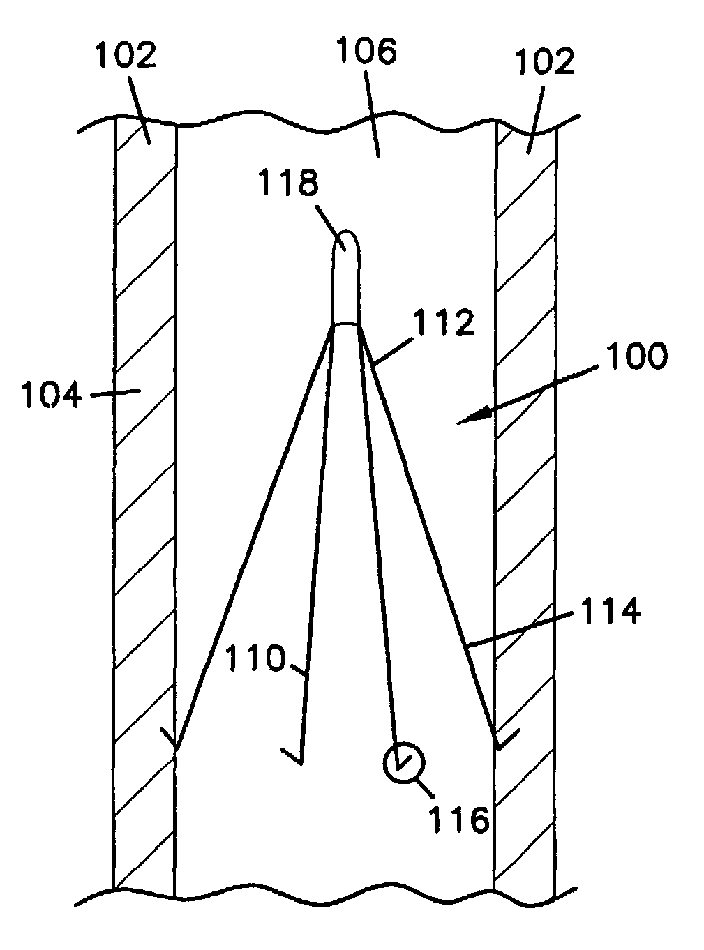
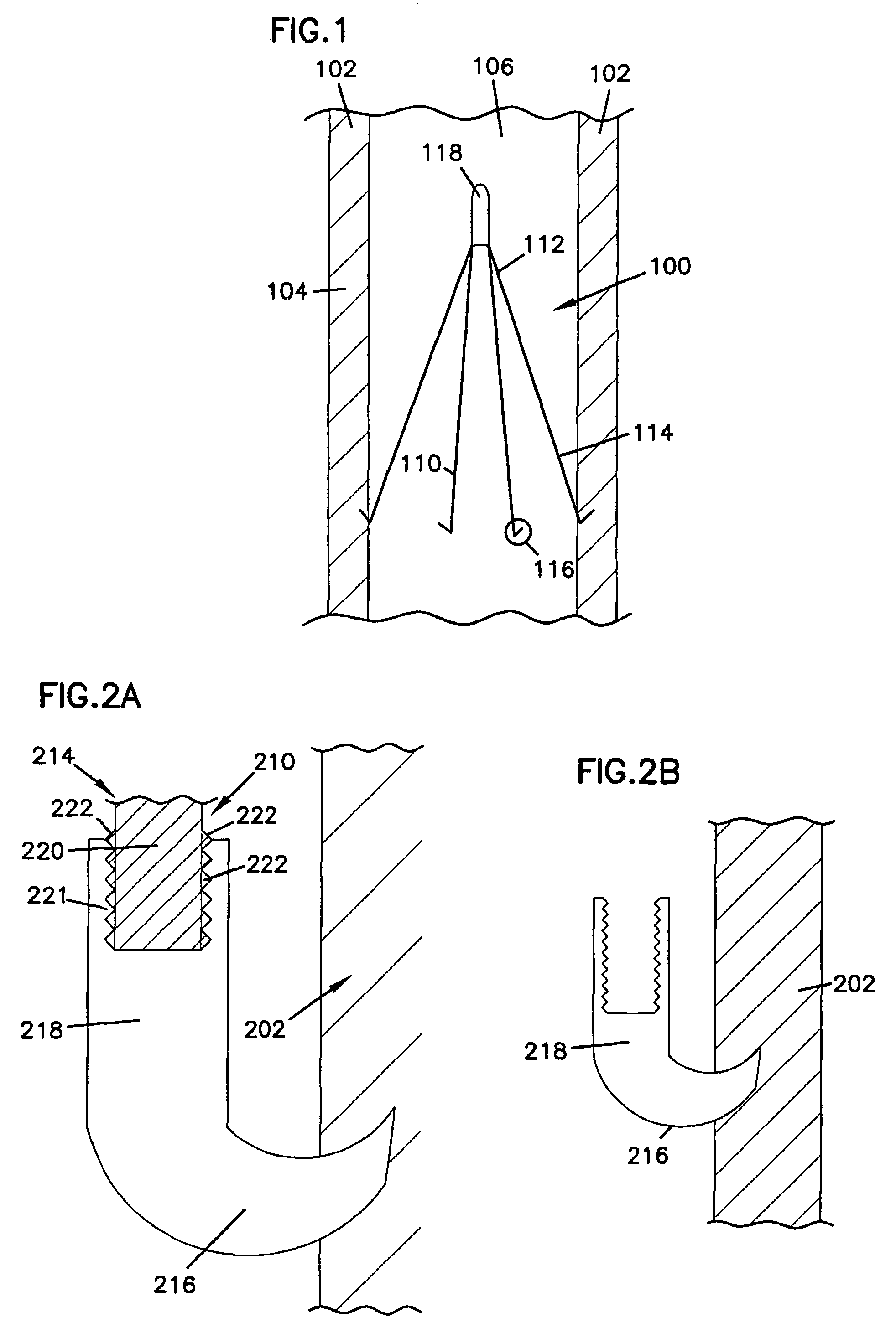
[0027]FIG. 1 depicts a venous filter 100 disposed in a blood vessel 104. The blood vessel 104 includes walls 102 that create a lumen 106. The venous filter 100, when deployed, is located within the lumen 106 and is anchored in some fashion within the walls 102.

[0028]The venous filter 100 has a generally conical shape. The venous filter 100 includes at least one strut 110 and a head 118. The number of struts 110, and the configuration of the struts 110 may vary depending on the particular type of venous filter 100. Each of the struts 110 has a connected end 112 and a non-connected end 114. The connected ends 114 of the struts 110 are connected by or within the head 118.

[0029]At least one of the struts 110 has an anchor 116 on the non-connected end 114. In some venous filters, such as that shown in FIG. 1, each of the struts 110 has an anchor 116 on the non-connected end 114. When deployed in a blood vessel 104, the non-connected ends 114 contact the wall 102. The anchors 116 then con...


PUM

PropertyMeasurementUnit
temperaturesaaaaaaaaaa
temperatureaaaaaaaaaa

Abstract

Venous filters having at least two struts (110) each having a connected end and a non-connected end, wherein each of the struts includes a strut portion and an anchor portion (116), and wherein the strut portion and the anchor portion are attached via an electrolytically active thread (221, 222); and a head (118) that connects the connected ends of the struts, wherein the strut portion can be separated from the anchor portion at least in part by the application of an electrical current. The invention also includes a venous filter having at least two struts, wherein each of the struts includes a temperature sensitive portion and an anchor portion; wherein the anchor portion is separated from the temperature sensitive portion at least in part by changing the temperature around at least the temperature sensitive portion. Also included is a venous filter having a web (650) of dissolvable material; and at least two anchors (618), wherein the at least two anchors are configured to retain the web within a mammalian blood vessel.

Description

[0001]This invention is supported by the Department of Health and Human Services. The Government of the United States of America may have certain rights in the invention disclosed and claimed herein below.[0002]This application is a National Stage Application of PCT / US2005 / 004076, filed 8 Feb. 2005, which is the International Application of Ser. No. 60 / 543,766, filed 9 Feb. 2004 and which application(s) are incorporated herein by reference. A claim of priority to both, to the extent appropriate is made.FIELD OF THE INVENTION[0003]The invention includes filters to remove clots from blood that are for use in mammalian veins. More particularly, the invention includes venous filters that are removable.BACKGROUND OF THE INVENTION[0004]Inferior vena cava (IVC) filters are devices that block the passage of venous emboli from the lower extremities or pelvis through the IVC into the pulmonary arteries. Generally, IVC filters are used to capture potentially fatal pulmonary emboli at an anatom...

Claims


Application Information

Patent Timeline
Patent Type & Authority Patents(United States)
IPC IPC(8): A61M29/00A61F2/00A61F2/01A61F2/02A61F2/06
CPCA61F2/01A61F2002/016A61F2002/8483A61F2210/0004A61F2210/0014A61F2250/003A61F2250/0059A61F2250/0071A61F2230/0006A61F2230/0067A61F2230/008A61F2/0105
Inventor NEEMAN, ZIVWOOD, BRADFORD J.
Owner UNITED STATES OF AMERICA
Why Eureka
Try Eureka