Supercharge Your Innovation With Domain-Expert AI Agents!

Parallel cyclic code generation device and parallel cyclic code error detection device

a generation device and cyclic code technology, applied in the direction of coding, code conversion, electrical equipment, etc., can solve the problems of increasing processing delay, increasing delay, and inability to obtain correct computations

Inactive Publication Date: 2011-01-11
NEC CORP
View PDF14 Cites 3 Cited by
  • Summary
  • Abstract
  • Description
  • Claims
  • Application Information

AI Technical Summary

Benefits of technology

This approach reduces processing delay, minimizes circuit size, and eases bandwidth constraints, enabling ultra-low delay CRC computation and error detection in high-speed data communications without the need for buffering, thus supporting broader bandwidth implementations.

Problems solved by technology

If parallel data containing the fraction bits is processed in a CRC calculation circuit of M bits, even invalid bits data other than the fraction bits will fall in a computation range of CRC codes, so that it is not possible to obtain a correct computation results.
Firstly, there will be an increase in processing delay. Inasmuch as buffering is executed in order to calculate a frame length, there is the need for buffering at least one frame or more. Accordingly, processing time for buffering, commensurate with the frame length, is required, resulting in an increase in delay
Secondly, there will be an increase in circuit size. As in the case of the configuration illustrated in FIG. 18, if the buffering unit 160-1, the read-out controller 160-2, the frame length counter 160-5, and the frame data rearrangement unit 160-3 are installed in the front stage of the CRC computation unit 160-4, this will cause a system in whole to increase in scale.
Thirdly, there will be constraints on implementation of a broader band. This problem is attributable to buffering of a broadband. An upper limit occurs to a processing band for buffering owing to band constraints of a memory in use and a circuit operating speed. In a frame communications technology of several tens of Gbps class, there are needs for not only an increase in the parallel width M of frame processing but also an increase in processing clock speed, but due to presence of constraints on an input / output band of the memory, in particular, broadening of the band is constrained. In the method for the parallel CRC computation, using buffering, illustrated in FIG. 18, the memory is used for the buffering, and constraints occur to the speed, so that constraints occur to the implementation of the broader band, as well.

Method used


Image

  • Parallel cyclic code generation device and parallel cyclic code error detection device
  • Parallel cyclic code generation device and parallel cyclic code error detection device
  • Parallel cyclic code generation device and parallel cyclic code error detection device

Examples


exemplary embodiment 1

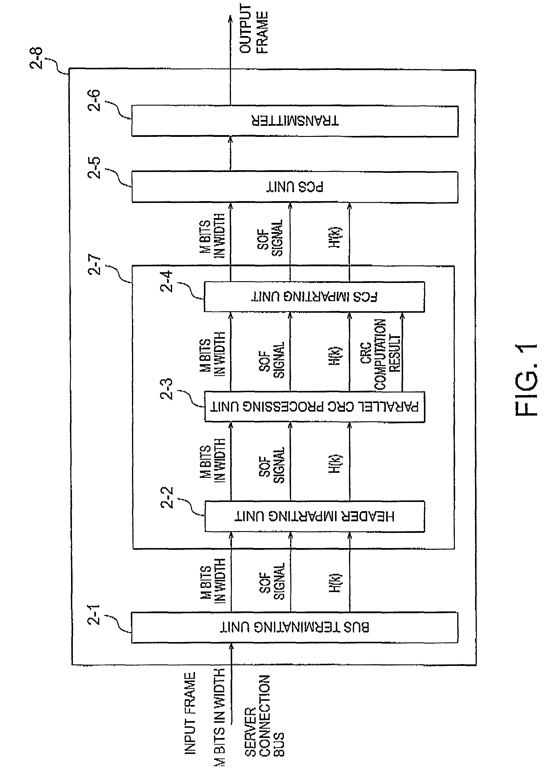
[0068]A first exemplary embodiment illustrates a parallel cyclic code generation device for executing an operation to generate the cyclic code. FIG. 1 is a block diagram showing a configuration example of a transmission function of a network interface card (NIC: Network Interface Card) to which the present invention is applied. The network interface card 2-8 illustrated in FIG. 1 includes the parallel cyclic code generation device for executing the operation to generate the cyclic code. The network interface card is a card mounted on a server, a computer, and so forth, for use in executing processing for transmitting and receiving frames.

[0069]The network interface card 2-8 according to the present invention comprises a bus terminating unit 2-1, a MAC framing unit 2-7, a PCS (Physical Coding Sublayer) unit 2-5, and a transmitter 2-6.

[0070]The MAC framing unit 2-7 executes processing for generation of transmission MAC frames. The MAC framing unit 2-7 comprises a header imparting unit...

exemplary embodiment 2

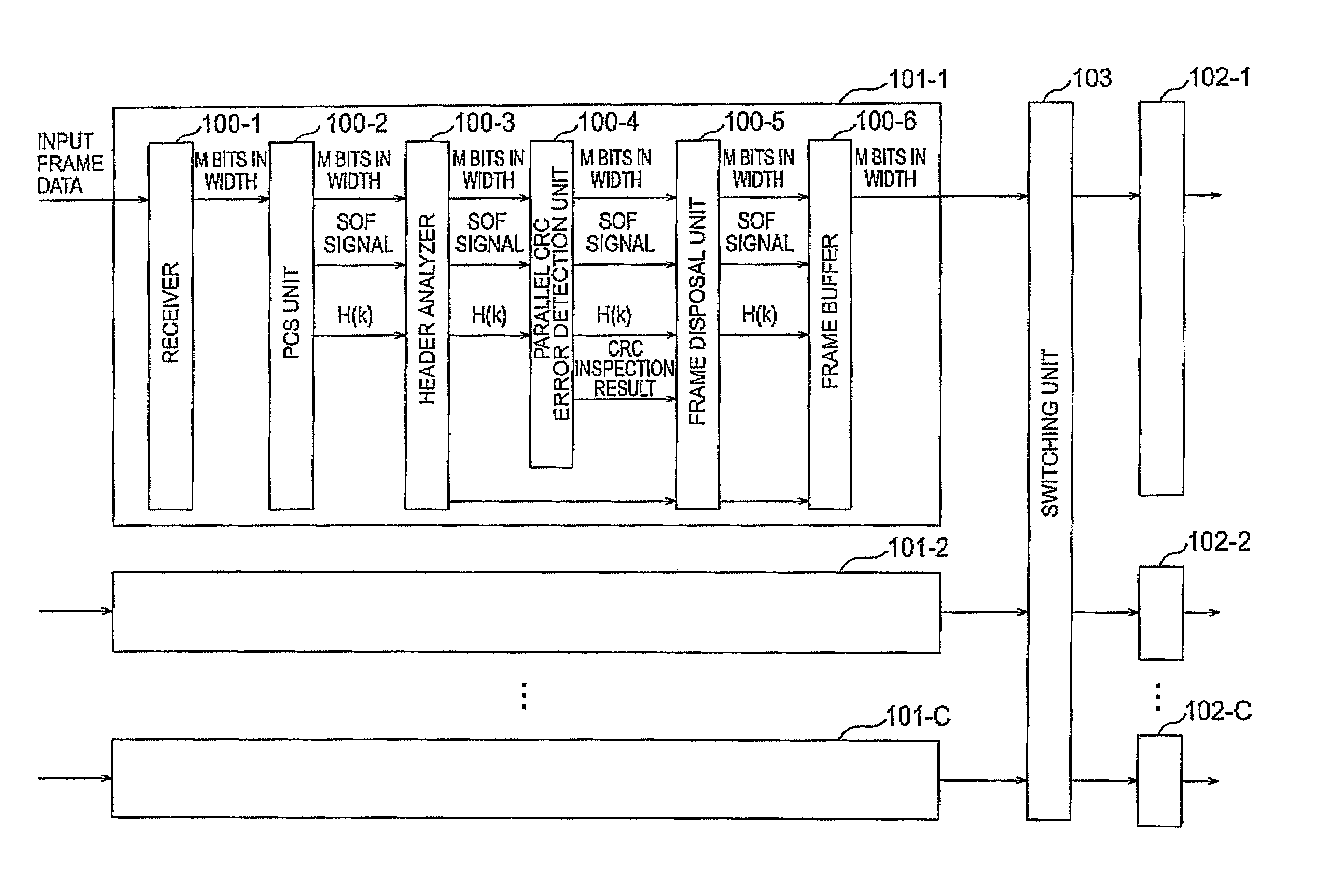
[0164]A second exemplary embodiment of the invention illustrates a parallel cyclic code error detection device for executing computation in order to inspect parallel cyclic codes. FIG. 10 is a block diagram showing an example of a configuration of an Ethernet switch to which the present invention is applied. The Ethernet switch illustrated in FIG. 10 comprises line card receivers 101-1 to 101-C, a switching unit 103, and line card transmitters 102-1 to 102-C. One line card receiver is paired off with one line card transmitter, and the number of the line card receiver and line card transmitter, in pairs, is denoted by C, where C represents an optional positive integer not less than 1. In FIG. 10, respective pairs of the line card receiver and line card transmitter are denoted by a number after hyphen in each of reference numerals ‘101-1’ to ‘101-C’, indicating the respective line card receivers. The same applied to reference numerals ‘102-1’ to ‘102-C’, indicating the respective line...


PUM


Abstract

To eliminate the need for buffering in order to calculate data length information on data as an object of computation, a first exclusive-OR unit 53 executes computation of exclusive-OR of a cyclic code R(x) of the integral multiple bit bits block A(x) and a data string of M bits, containing the fraction bits block B(x). A first shifting unit 54 shifts the exclusive-OR of the cyclic code R(x) and the data string of M bits, containing the fraction bits block B(x), by {M−H(k)} bits toward a least significant side, where M is a parallel width and H(k) is a bit length of the fraction bits block B(x). An R′(x) generation unit 55 generates a cyclic code R′(x) that is a cyclic code of the data after shifting. To obtain R″(x), a second shifting unit 56 shifts the cyclic code R(x) by H(k) bits toward a most significant side. A second exclusive-OR unit 57 executes computation of exclusive-OR of the cyclic code R′(x) and data R″(x).

Description

[0001]This application is based upon and claims the benefit of priority from Japanese patent application No. 2007-220948, filed on Aug. 28, 2007, the disclosure of which is incorporated herein in its entirety by reference.BACKGROUND OF THE INVENTION[0002]1. Field of the Invention[0003]The invention relates to a parallel cyclic code generation device for generating a cyclic code for use in detecting a bit error inside transfer frames in data communications, and also relates to a parallel cyclic code error detection device for inspecting a cyclic code for use in detecting a bit error inside transfer frames in data communications.[0004]2. Description of Related Art[0005]In recent years, there have been advances in broader bandwidths for a frame rate in data communications technology including 40 Gigabit Ethernet, and 100 Gigabit Ethernet, as specified by U.S. IEEE 802 committee. Herein, Ethernet is a registered trademark. In processing for the frame rate in broader bandwidths, there ar...

Claims


Application Information

Patent Timeline
Patent Type & Authority Patents(United States)
IPC IPC(8): H03M13/00
CPCH03M13/091
Inventor SHIGIHARA, MASAHIROTAKAMICHI, TORU
Owner NEC CORP
Features
  • R&D
  • Intellectual Property
  • Life Sciences
  • Materials
  • Tech Scout
  • Unparalleled Data Quality
  • Higher Quality Content
  • 60% Fewer Hallucinations
Learn More