Exhaust gas turbocharger for an internal combustion engine

a technology of exhaust gas and internal combustion engine, which is applied in the direction of liquid fuel engines, vessel construction, marine propulsion, etc., can solve the problems of reducing increase the mass moment of inertia of the compressor wheel, and increase the efficiency of the exhaust gas turbocharger in cold-air turbine mode. , the effect of reducing the speed fluctuations of the exhaust gas turbocharger

Inactive Publication Date: 2011-01-18
DAIMLER AG
View PDF20 Cites 9 Cited by
  • Summary
  • Abstract
  • Description
  • Claims
  • Application Information

AI Technical Summary

Benefits of technology

[0007]The contoured ring is attached to the compressor wheel blades. As a result of the arrangement of the contoured ring, which is provided with auxiliary blades in the wheel inlet region of the compressor wheel, the efficiency of the exhaust gas turbocharger at low speeds and / or low loads of the internal combustion engine can be increased. In addition, the contoured ring with the auxiliary blades increases a mass moment of inertia of the compressor wheel, as a result of which speed fluctuations of the exhaust gas turbocharger can be reduced.
[0008]In a further embodiment of the invention, the contoured ring with the auxiliary blades is embodied as a cold-air turbine wheel zone structure with a radial in-flow arrangement. In this way, it is possible in particular in the cold-air turbine mode to obtain an increase in efficiency of the exhaust gas turbocharger.
[0010]The axial blade contour of the auxiliary blades may be configured such that, proceeding from the end of the contoured ring which faces toward the compressor wheel outlet to a certain apex of the axial blade contour, a first blade angle of the auxiliary blades corresponds to a blade angle of the compressor wheel blades of the compressor wheel, and such that, proceeding from the apex to an end of the contoured ring which faces away from the compressor wheel outlet, the auxiliary blades have a second blade angle which differs from the first blade angle. As a result of the change in the blade angle of the auxiliary blades from a first blade angle into a second blade angle, a hook-shaped blade contour of the auxiliary blades is generated, as a result of which the flow of the intake air is aligned such that the intake air flows almost entirely via the contoured ring and a cold-air turbine wheel outlet into a compressor wheel outlet. The hook-shaped blade contour prevents a flow of the intake air via the end of the contoured ring which faces away from the compressor wheel outlet and into the axial wheel inlet region. In order to avoid an improper approach of the flow to the auxiliary blades, the apex of the blade angle change is situated, with a slight axial deviation, at the level of a characteristic edge of a guide vane structure of a variable compressor geometry.
[0013]The outer diameter or the inner diameter and the outer diameter of the contoured ring increases continuously proceeding from the apex to an end of the contoured ring which faces away from the compressor wheel outlet of the compressor wheel. In this way, the lateral surface of the contoured ring has a curved shape. As a result of said curved shape of the contoured ring, a blade height of the auxiliary blades reduces likewise continuously corresponding to the increase in the outer diameter of the contoured ring. The shape of the contoured ring likewise prevents, like the hook-shaped blade contour of the auxiliary blades, a flow of the intake air via the end of the contoured ring which faces away from the compressor wheel outlet of the compressor wheel and into the axial wheel inlet region of the compressor wheel.
[0015]The outer diameter or the inner diameter and the outer diameter of the contoured ring increases continuously proceeding from the apex to an end of the contoured ring which faces toward the compressor wheel outlet of the compressor wheel. In this way, the lateral surface of the contoured ring likewise has a curved shape. As a result of said curved shape of the contoured ring, the blade height of the auxiliary blades reduces likewise continuously corresponding to the increase in the outer diameter of the contoured ring. The shape of the contoured ring promotes a direct flow of the intake air into the compressor wheel outlet and prevents the flow of the intake air via the end of the contoured ring which faces away from the compressor wheel outlet of the compressor wheel and into the axial wheel inlet region of the compressor wheel.
[0016]Additional blades may be arranged between the auxiliary blades on the contoured ring. As a result of the provision of additional blades, the efficiency of the exhaust gas turbocharger in the cold-air turbine mode can be further increased. In addition, the additional blades increase the mass moment of inertia of the compressor wheel, so that speed fluctuations of the exhaust gas turbocharger can be further reduced.

Problems solved by technology

As a result of the transition of the auxiliary blades into the compressor wheel blades, there is no flow separation of the intake air, which could cause turbulence that would reduce the exhaust gas turbocharger efficiency, either at low speeds and / or low loads of the internal combustion engine, or at medium to high speeds and / or loads of the internal combustion engine, or in the cold-air turbine mode of the exhaust gas turbocharger.

Method used


Image

  • Exhaust gas turbocharger for an internal combustion engine
  • Exhaust gas turbocharger for an internal combustion engine
  • Exhaust gas turbocharger for an internal combustion engine

Examples


Embodiment Construction

[0025]In the following figures, identical or equivalent components are provided with the same reference symbols.

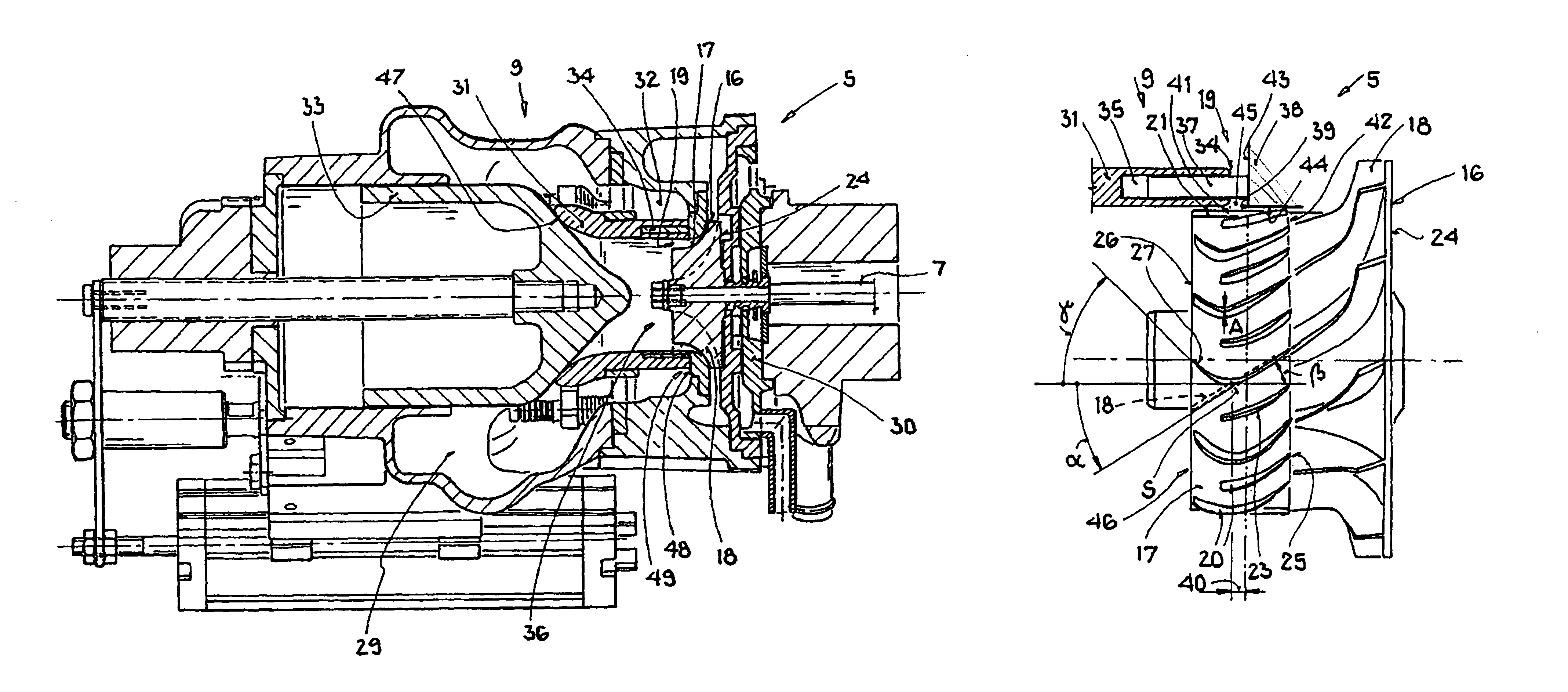
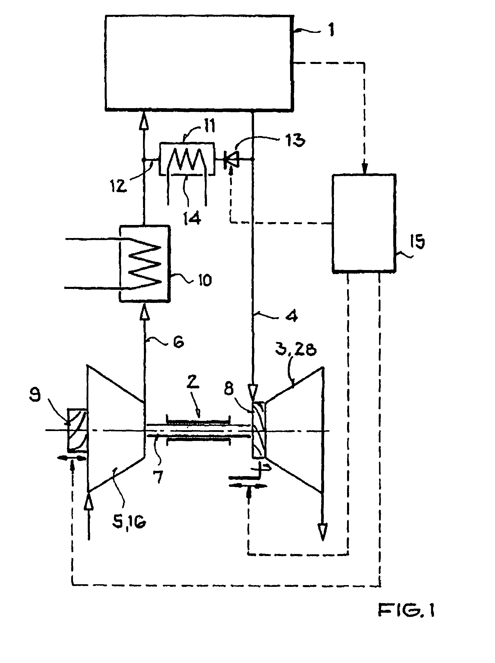
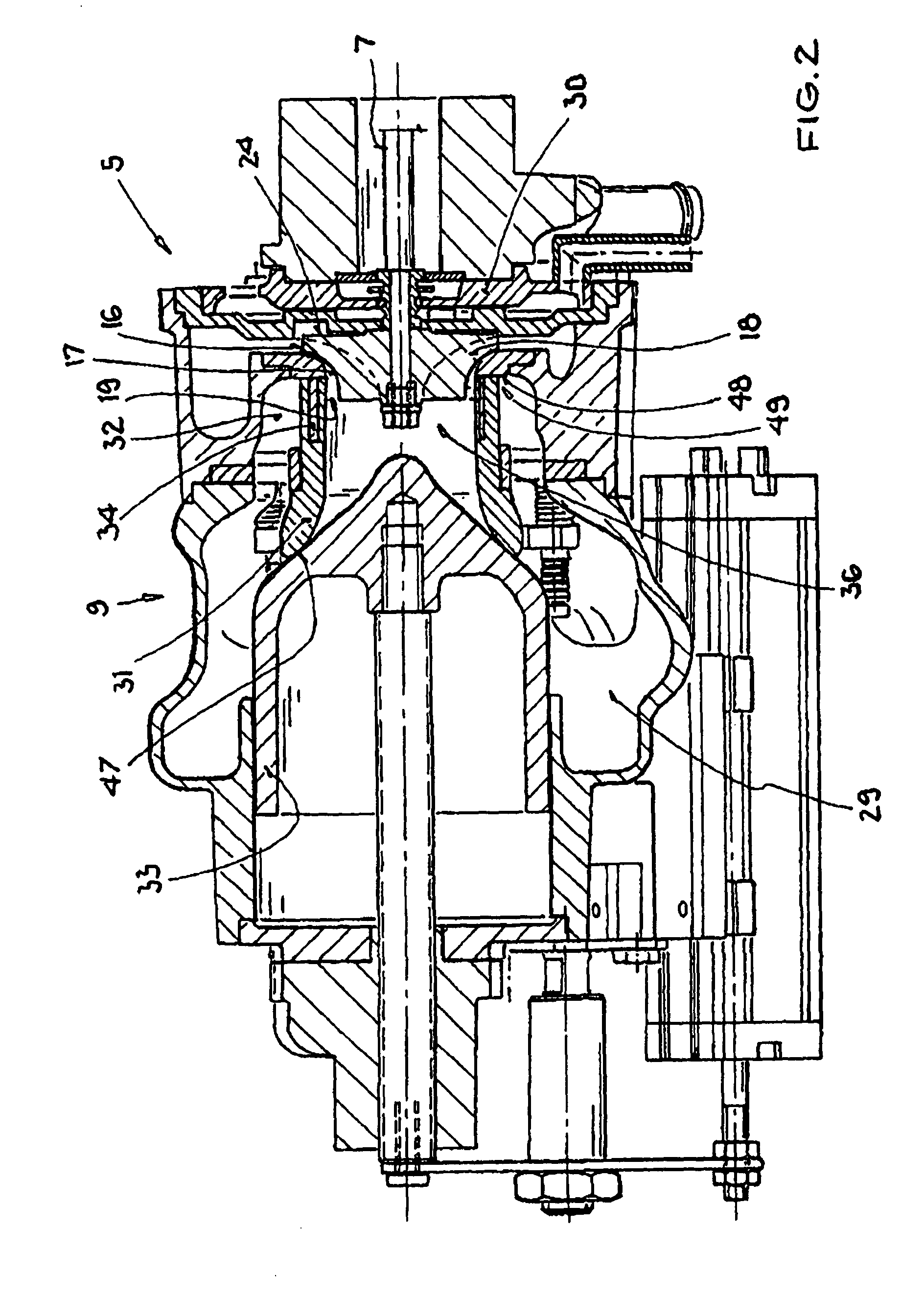
[0026]The internal combustion engine 1 illustrated in FIG. 1, a spark-ignition engine or a diesel engine, is provided with an exhaust gas turbocharger 2 which comprises a turbine 3 in an exhaust tract 4 of the internal combustion engine 1 and a compressor 5 in an intake tract 6 of the internal combustion engine 1. A turbine wheel 28 of the turbine 3 is rotationally fixedly connected by means of a shaft 7 to a compressor wheel 16 of the compressor 5. The turbine 3 is provided with a variable turbine geometry 8 for the variable adjustment of the effective turbine inlet cross section between a minimal, blocking position and a maximum open position. The compressor 5 is provided with a variable compressor geometry 9 for the variable adjustment of the effective compressor inlet cross section between a minimal and a maximum open position.

[0027]In operation of the internal combust...


PUM


Abstract

In an exhaust gas turbocharger for an internal combustion engine having a turbine wheel connected, by means of a shaft, to the compressor wheel of a compressor which includes a variable inlet geometry comprising a plunger and a sleeve-shaped partition for controlling an auxiliary duct leading radially to the compressor wheel, which is provided with compressor wheel blades to which air is supplied axially via an axial inlet passage and radially via a radial wheel inlet area, the compressor wheel includes a contoured ring provided at its outer circumferential surface with auxiliary blades disposed over, and aligned with, the compressor wheel blades in the radial and the axial wheel inlet region of the compressor wheel.

Description

[0001]This is a Continuation-In-Part application of pending international patent application PCT / EP2006 / 003560 filed Apr. 19, 2006 and claiming the priority of German patent application 10 2005 019 938.0 filed Apr. 29, 2005.BACKGROUND OF THE INVENTION[0002]The invention relates to an exhaust gas turbocharger for an internal combustion engine having a turbine wheel and a compressor wheel mounted on a common shaft, wherein the compressor wheel is disposed in a housing having an inlet with an adjustable inlet structure for controlling the air flow to the compressor wheel.[0003]Such an exhaust gas turbocharger is described in DE 100 49 198 A1. This exhaust gas turbocharger comprises a compressor in the intake tract of an internal combustion engine, which compressor is driven via a shaft by a turbine disposed in the exhaust tract. In the turbine, the energy of the exhaust gas is converted into a rotary movement of the turbine wheel. The turbine wheel of the turbine is rotationally fixedl...

Claims


Application Information

Patent Timeline
Patent Type & Authority Patents(United States)
IPC IPC(8): F02B33/44F04D29/42F04D29/66F04D29/40F04D29/38
CPCF01D5/022F01D17/143F02C3/073F02C6/12F04D29/284F04D29/4213
Inventor FLEDERSBACHER, PETERHIRTH, TORSTENSUMSER, SIEGFRIED
Owner DAIMLER AG
Why Eureka
Try Eureka