Rear wheel toe angle control device

a control device and rear wheel technology, applied in the direction of process and machine control, braking system, instruments, etc., can solve the problems of reducing the pneumatic pressure of tires, and affecting the performance of temporary tires, etc., to achieve stable steering performance.

Inactive Publication Date: 2011-01-18
HONDA MOTOR CO LTD
View PDF18 Cites 5 Cited by
  • Summary
  • Abstract
  • Description
  • Claims
  • Application Information

AI Technical Summary

Benefits of technology

[0006]In view of such problems of the prior art, a primary object of the present invention is to provide a rear wheel toe angle control device that can ensure a stable steering performance even when the cornering powers of laterally opposing rear wheels are different from each other.
[0009]According to the present invention, when one of the rear wheel demonstrates a reduced cornering power, the slip angle of the other rear wheel is increased because the other rear wheel is likely to have a margin to produce an increased amount of cornering power that can make up for the reduction of the cornering power of the one rear wheel. Thereby, the combined cornering power of the two rear wheels can be maintained at a normal level, and it allows the steering performance of the vehicle when making a turn to remain the same in spite of the diminished performance of the one rear wheel. This also contributes to a stable running performance of the vehicle.

Problems solved by technology

It is known that the pneumatic pressure of a tire can decrease over time depending on the mileage, driving condition and road condition, and this may impair the performance of the tire.
Also, a temporary tire typically wears much faster than a normal tire, and this further diminishes the performance of the tire.
The steering property differs depending on the direction of the turn, and a vehicle operator experiences a significant difficult in slaloming the vehicle in a stable manner.

Method used


Image

  • Rear wheel toe angle control device
  • Rear wheel toe angle control device
  • Rear wheel toe angle control device

Examples


Embodiment Construction

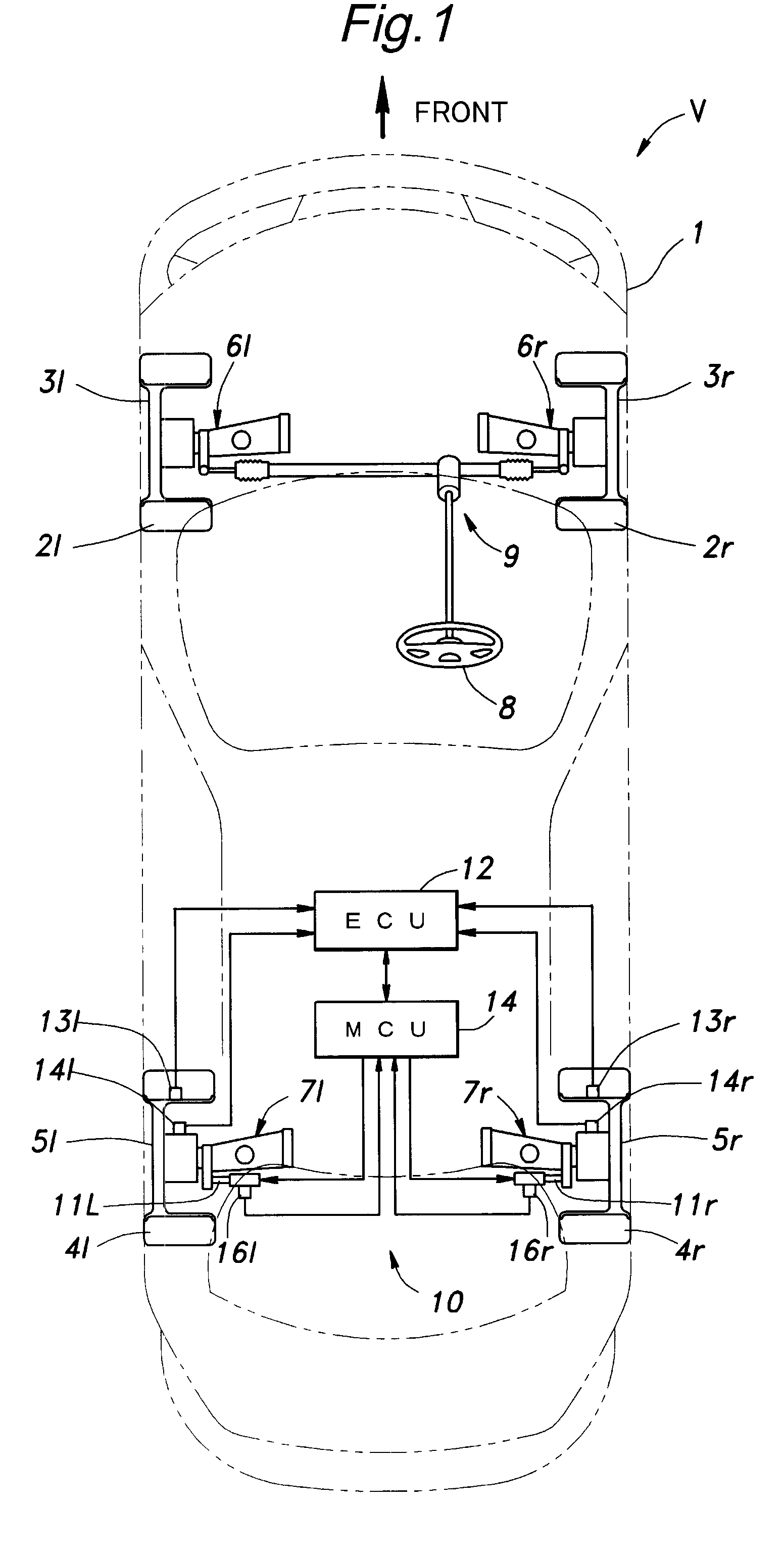
[0021]FIG. 1 shows a vehicle incorporated with a rear wheel toe angle control device embodying the present invention. In FIG. 1, each wheel and associated components such as a tire and a suspension system are denoted with suffixes such as “r” and “l” in addition to the corresponding numeral to indicate the positioning of the corresponding component such as “left rear wheel 5l and right rear wheel 5r”. When the various components are generally referred to, they are collectively denoted only with the corresponding numeral such “rear wheels 5”.

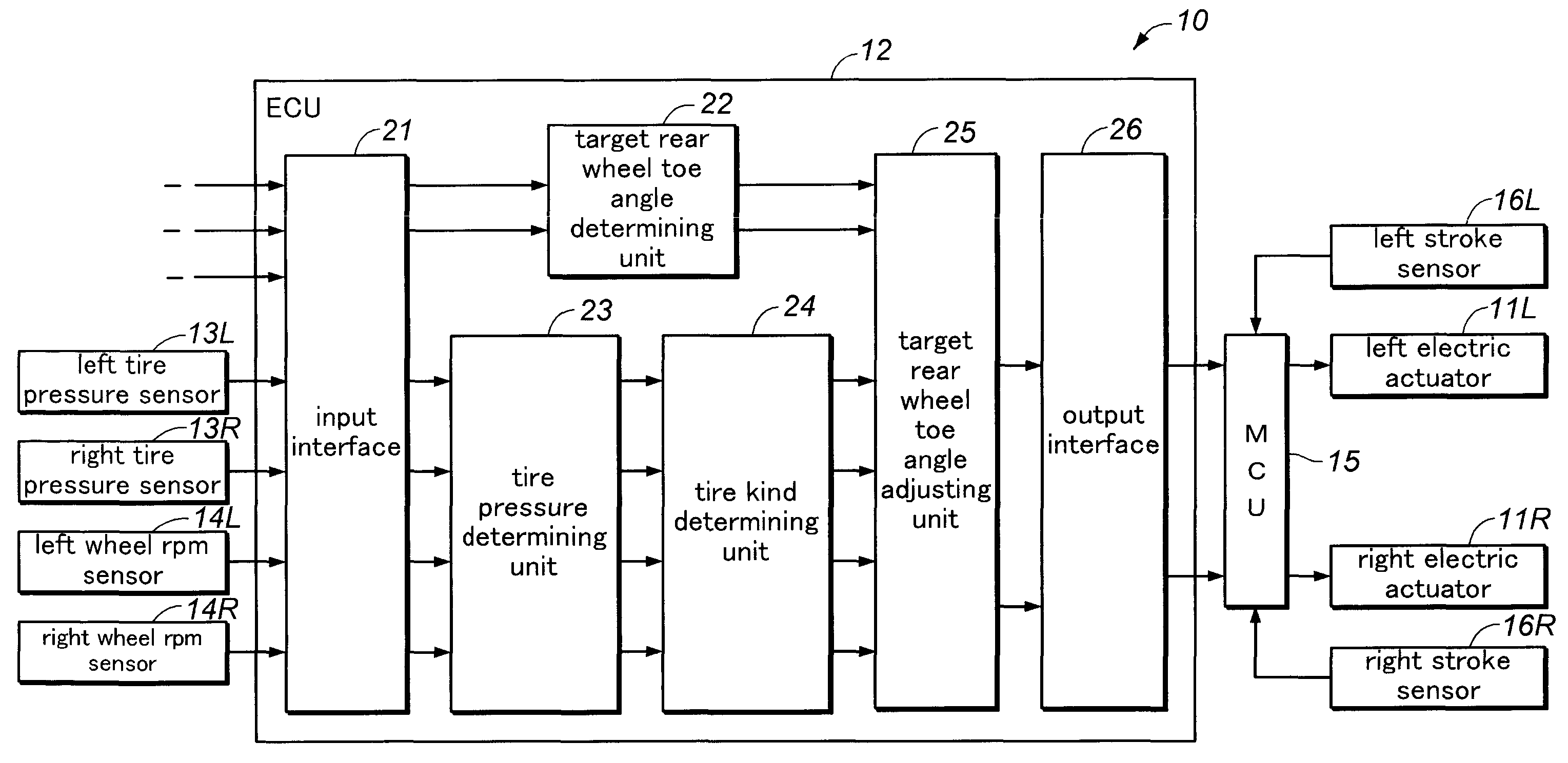
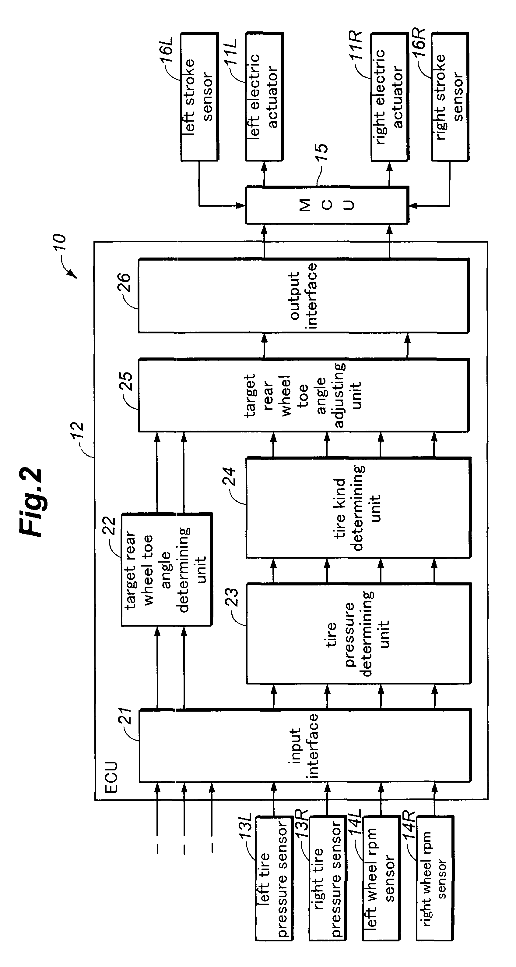
[0022]FIG. 1 is a schematic diagram of a motor vehicle V equipped with a rear wheel toe angle control device 10 embodying the present invention, and FIG. 2 is a functional block diagram of the rear wheel toe angle control device 10. Referring to FIG. 1, the vehicle (rear wheel steering vehicle) V comprises a pair of front wheels 3l and 3r fitted with tires 2l and 2r, respectively, and rear wheels 5l and 5r fitted with tires 4l and 4r, respectivel...


PUM


Abstract

A rear wheel toe angle control device that ensures a stable steering performance even when the cornering powers of laterally opposing rear wheels are different from each other. When a reduction in the cornering power of one of the rear wheels owing to a drop in the tire pressure or a temporary tire is determined, a control unit changes the toe angle of the other rear wheel in a direction to increase the slip angle of thereof, and additionally changes the toe angle of the one rear wheel in a direction to decrease the slip angle of thereof. The combined cornering power of the two rear wheels is maintained at a normal level, and the steering performance of the turning vehicle remains the same. This also contributes to a stable running performance of the vehicle, and a maximization of the total available cornering power of the rear wheels.

Description

TECHNICAL FIELD[0001]The present invention relates to a rear wheel toe angle control device for controlling a rear wheel toe angle in a variable rear wheel toe angle vehicle, and in particular to a technology that controls a rear wheel toe angle depending on changes in the cornering power of rear wheels.BACKGROUND OF THE INVENTION[0002]In a four wheel vehicle, the front wheels are steered for changing the traveling direction of the vehicle, and are additionally given with a certain toe angle so as to ensure a motion stability of the vehicle. In recent years, it has also been proposed to control the toe angle of the rear wheels for the purpose of improving the stability of the vehicle when braking and the responsiveness when accelerating, and improving the heading response of the vehicle at the time of a low speed turn and the stability of the vehicle at the time of a high speed turn.[0003]A typical toe angle control device mounted on such a vehicle includes an electric linear actuat...

Claims


Application Information

Patent Timeline
Patent Type & Authority Patents(United States)
IPC IPC(8): B62D6/00
CPCB62D6/006B62D7/159
Inventor SASAKI, HIROAKI
Owner HONDA MOTOR CO LTD
Why Eureka
Try Eureka