Bubble separator

a separator and bubble technology, applied in the direction of separation process, liquid degasification, filtration separation, etc., can solve the problems of fluid blowing away from the gas discharge hole, poor lubrication, and poor lubrication, so as to achieve efficient separation, high efficiency, and easy separation

Inactive Publication Date: 2011-01-18
TOYOTA BOSHOKU KK
View PDF7 Cites 5 Cited by
  • Summary
  • Abstract
  • Description
  • Claims
  • Application Information

AI Technical Summary

Benefits of technology

[0025]According to the bubble separator of the present invention, a centrifugal bubble separating mechanism and an auxiliary bubble separating mechanism, which has a guiding portion for changing the flow direction of introduced fluid and a different form from the centrifugal bubble separating mechanism, are provided. Therefore, in addition to minuscule bubbles it is also possible to separate large bubbles that could not be completely separated using the centrifugal bubble separating mechanism. Furthermore, even in cases where bubbles would remain because the centrifugal bubble separating mechanism alone is unable to separate a large amount of bubbles, the present invention can separate many bubbles with extremely high efficiency.
[0026]When the centrifugal bubble separating mechanism is provided upstream and the auxiliary bubble separating mechanism is provided downstream, small bubbles are efficiently separated upstream. Meanwhile, large bubbles or residual bubbles left from a large amount of bubbles which were not separated upstream are reliably and easily separated by the downstream separating mechanism. Therefore, all bubbles can be efficiently separated.
[0027]When the centrifugal bubble separating mechanism is provided downstream and the auxiliary bubble separating mechanism is provided upstream, the bubbles are ultimately separated in an efficient manner similar to the above, regardless of whether there are large bubbles or a large amount of bubbles.
[0028]If the guiding portion is a partition formed from a board-shaped body, then it is possible to achieve a simple structure, and further possible to efficiently separate bubbles from the fluid.
[0029]A longer separation distance and separation time are possible when the auxiliary bubble separating mechanism is a flow passage of the bent body provided with the gas discharging part on an upper wall face thereof. Therefore, bubble separation can be even more efficiently and reliably achieved in the auxiliary separating mechanism.
[0030]If the second fluid discharging part in the auxiliary bubble separating mechanism is an opening and closing valve that opens and closes depending on the pressure within the first bubble separator body, then bubbles can be more conveniently and efficiently separated from the fluid.

Problems solved by technology

However, in the dry sump system a considerable amount of air bubbles are mixed into the oil while it is being returned to the oil tank via the scavenge pump.
The bubbles contained in the oil are subsequently separated by an oil filter or the like, but there is a risk of poor lubrication due to incomplete separation.
In such case, there is a risk that poor lubrication may occur because air bubbles have not been sufficiently eliminated.
But if there is little gas, then the fluid is blown away from the gas discharge holes.
In other words, many or large bubbles makes full separation of the bubbles and the fluid difficult as some bubbles are discharged together with the fluid.
As a consequence, efficient bubble separation cannot be achieved.

Method used


Image

  • Bubble separator
  • Bubble separator
  • Bubble separator

Examples


embodiments

[0077]The present invention will be described in detail below based on embodiments and in reference to the accompanying drawings.

[0078]Note that in the present embodiments, examples are given of a bubble separator according to the present invention which is used in a lubrication system of an automotive engine and separates bubbles from oil mixed with bubbles.

first embodiment

[1] First Embodiment

(1) Structure of the Bubble Separator 1

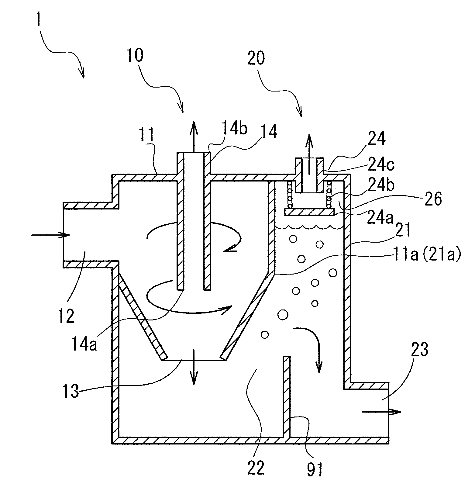
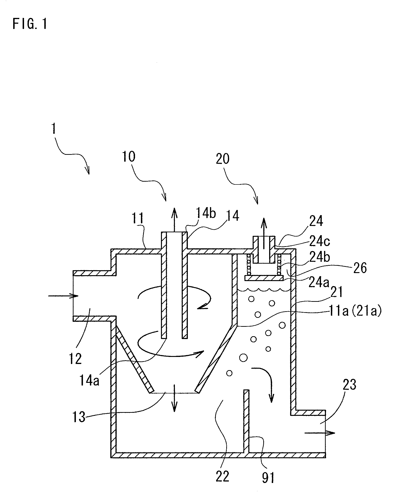
[0079]As shown in FIG. 1, a bubble separator 1 according to the present invention has a centrifugal bubble separating mechanism 10 and an auxiliary bubble separating mechanism 20 provided downstream thereof.

[0080]The centrifugal bubble separating mechanism 10 has a first bubble separator body 11, and a first fluid introducing part 12 that introduces oil (oil containing bubbles) into a cyclone separation chamber inside the first bubble separator body 11 in the tangential direction.

[0081]Furthermore, a first fluid discharging part 13 that discharges oil separated by swirling (primary separated oil containing residual bubbles) is provided in the lower portion of the cyclone chamber. Also a first gas discharging part 14 that discharges bubbles (gas) separated by swirling is provided forming in a cylindrical and tubular body extending from the upper portion toward the lower portion of the cyclone chamber.

[0082]The auxiliary bubbl...

second embodiment

[2] Second Embodiment

(1) Structure of the Bubble Separator 2

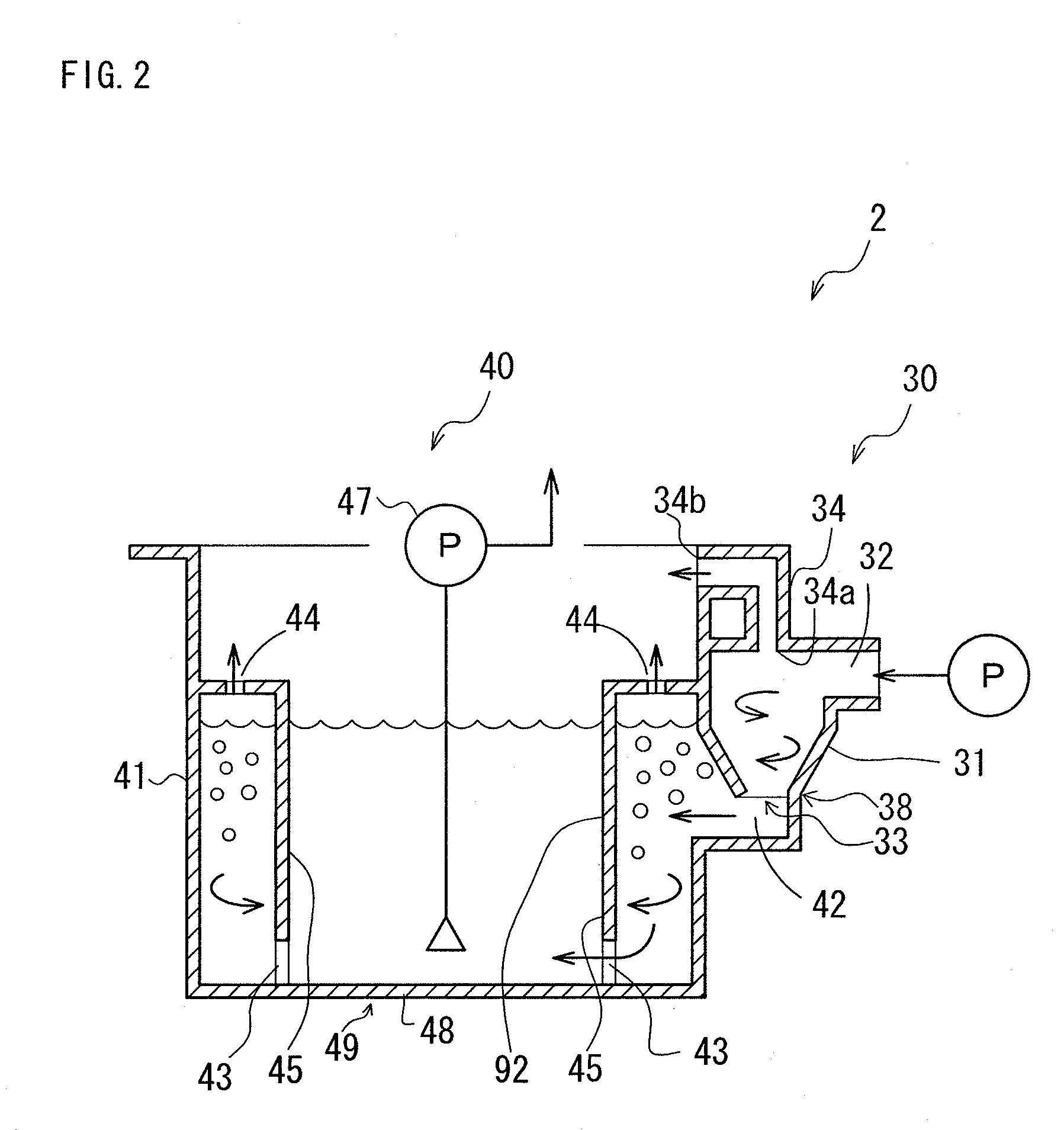
[0092]As shown in FIG. 2, a bubble separator 2 according to the present invention has a centrifugal bubble separating mechanism 30 and an auxiliary bubble separating mechanism 40 provided downstream thereof, similar to the first embodiment.

[0093]The centrifugal bubble separating mechanism 30 has a first bubble separator body 31, a first fluid introducing part 32 that introduces oil (oil containing bubbles) inside the first bubble separator body 31 in the tangential direction, a first fluid discharging part 33 that discharges oil separated by swirling (primary separated oil containing residual bubbles), and a first gas discharging part 34 that discharges bubbles (gas) separated by swirling.

[0094]The auxiliary bubble separating mechanism 40 has a second bubble separator body 41, a second fluid introducing part 42 that introduces oil (primary separated oil containing residual bubbles) to the second bubble separator body 41, a ...


PUM

PropertyMeasurementUnit
diameteraaaaaaaaaa
diameteraaaaaaaaaa
inclined angleaaaaaaaaaa

Abstract

A bubble separator capable of performing efficient bubble separation with a compact and simple structure is provided. The bubble separator includes a centrifugal bubble separating mechanism and an auxiliary bubble separating mechanism. The centrifugal bubble separating mechanism has a first bubble separator body in which a first fluid introducing part, a first fluid discharging part, and a first gas discharging part are provided. The auxiliary bubble separating mechanism has a guiding portion, a second bubble separator body, a second fluid introducing part, a second fluid discharging part, and a second gas discharging part. According to the bubble separator of the present invention, in addition to minuscule bubbles it is also possible to separate large bubbles that could not be completely separated using the centrifugal bubble separating mechanism.

Description

BACKGROUND OF THE INVENTION[0001]1. Field of the Invention[0002]The present invention relates to a bubble separator. More specifically, the present invention relates to a bubble separator with a compact and simple structure, which is capable of improving a bubble separation efficiency even when there are bubbles of various sizes contained in a fluid. The bubble separator according to the present invention is used in a lubrication system of an internal combustion engine, and is also applicable to food, paint, and other fields.[0003]2. Description of the Related Art[0004]Dry sump and wet sump systems are commonly known as modes for lubricating internal combustion engines. The dry sump system is a type in which engine oil collects in an oil tank and the engine oil is sent under pressure from the oil tank through a feed pump to lubricate respective parts of the engine. Oil that falls into an oil pan is then returned to the oil tank through a scavenge pump. The wet sump system is a type ...

Claims


Application Information

Patent Timeline
Patent Type & Authority Patents(United States)
IPC IPC(8): B01D19/00
CPCB01D19/0042B01D19/0057G01N30/40G01N2030/402
Inventor SAITO, YASUHIRO
Owner TOYOTA BOSHOKU KK
Why Eureka
Try Eureka