Ultrasonic probe, ultrasonic flaw detection method, and ultrasonic flaw detection apparatus

a flaw detection and ultrasonic technology, applied in the field of ultrasonic probes, can solve the problems of reducing the s/n ratio of flaw echo, complicated waveform of received signal, and increasing the strength of reflected echo from minute flaws, so as to achieve high accuracy and ensure the detection of high-accuracy angle beam flaws. , the effect of increasing the strength of reflected echo

Inactive Publication Date: 2011-01-25
NIPPON STEEL CORP
View PDF23 Cites 11 Cited by
  • Summary
  • Abstract
  • Description
  • Claims
  • Application Information

AI Technical Summary

Benefits of technology

[0044]According to the present invention, by disposing an ultrasonic probe according to the present invention in a suitable location with respect to a tubular metal body being inspected, particularly even with a high t / D metal pipe for which the ratio (t / D) is at least 15%, among the refracted waves propagating inside the tubular body being inspected, refracted transverse waves can be focused on the inner surface of the tubular body being inspected, while refracted longitudinal waves can be prevented from reaching it. Therefore, the strength of reflected echoes from minute flaws is increased by focusing the refracted transverse waves, while the occurrence of multiply reflected echoes due to refracted longitudinal waves can be eliminated because the refracted longitudinal waves follow a path of propagation which does not reach the inner surface of the tubular body being inspected. As a result, high-accuracy angle beam flaw detection can be carried out with certainty, particularly on high t / D metal pipes.
[0045]In this manner, according to the present invention, flaw detection of minute flaws present inside a tubular body being inspected and particularly inside a high t / D metal pipe for which the ratio (t / D) is at least 15% can be carried out with high accuracy and with certainty by angle beam flaw detection without a decrease in detecting efficiency or an increase in detection costs.BRIEF EXPLANATION OF THE DRAWINGS
[0046]FIG. 1(a) is an explanatory view comparing the longitudinal cross-sectional shape of the front end portion of an improved transducer conceived by the present inventor to the longitudinal cross-sectional shape of the front end portion of a conventional transducer, and FIG. 1(b) is an explanatory view comparing the state of angle beam flaw detection of a high t / D metal pipe using this improved transducer and the state of angle beam flaw detection of a high (t / D) metal pipe using the conventional transducer.
[0047]FIG. 2 is a block diagram schematically showing the structure of an embodiment of an ultrasonic flaw detection apparatus.
[0048]FIG. 3 is a block diagram schematically showing the steps in designing the shape of the front end portion of a transducer.
[0049]FIG. 4A is an explanatory view showing a step in designing the shape of the front end portion of a transducer when a high t / D metal pipe with an outer diameter of 40 mm and a wall thickness of 10 mm is the object being inspected.

Problems solved by technology

As a result, the location of a flaw cannot be specified, the wave shape of a received signal becomes complicated, and the S / N ratio of a flaw echo decreases.
However, when the second transducer is used, not only refracted transverse waves but also refracted longitudinal waves are generated, so the position of a flaw can not be specified, the waveform of the received signal becomes complicated, or the S / N ratio of flaw echoes decreases.

Method used


Image

  • Ultrasonic probe, ultrasonic flaw detection method, and ultrasonic flaw detection apparatus
  • Ultrasonic probe, ultrasonic flaw detection method, and ultrasonic flaw detection apparatus
  • Ultrasonic probe, ultrasonic flaw detection method, and ultrasonic flaw detection apparatus

Examples


first embodiment

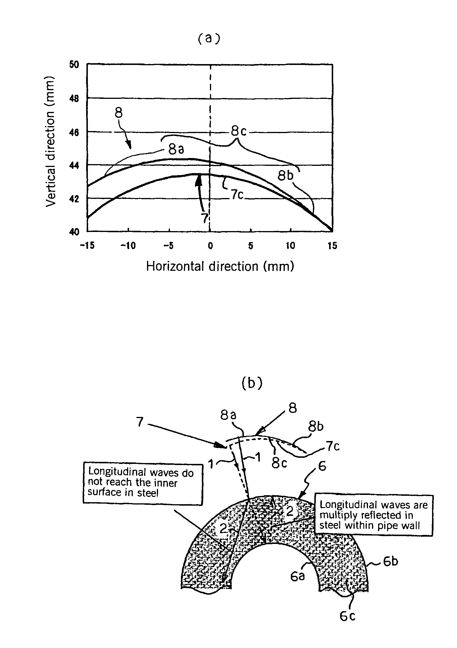
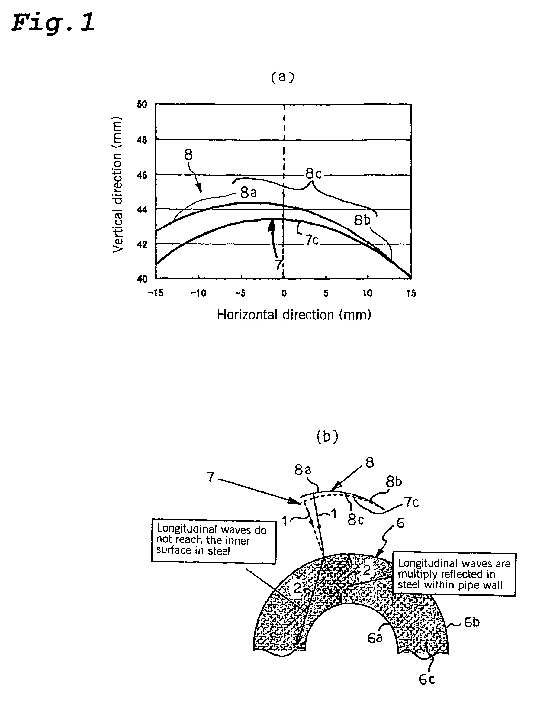
[0125]Below, a best mode for carrying out an ultrasonic probe, an ultrasonic flaw detection method, and an ultrasonic flaw detection apparatus according to the present invention will be explained in detail while referring to the attached drawings. In the following explanation, an example will be given of the case in which a tubular metal body being inspected is a high t / D metal pipe 16 for which the ratio (t / D) of the wall thickness t to the outer diameter D is at least 15%.

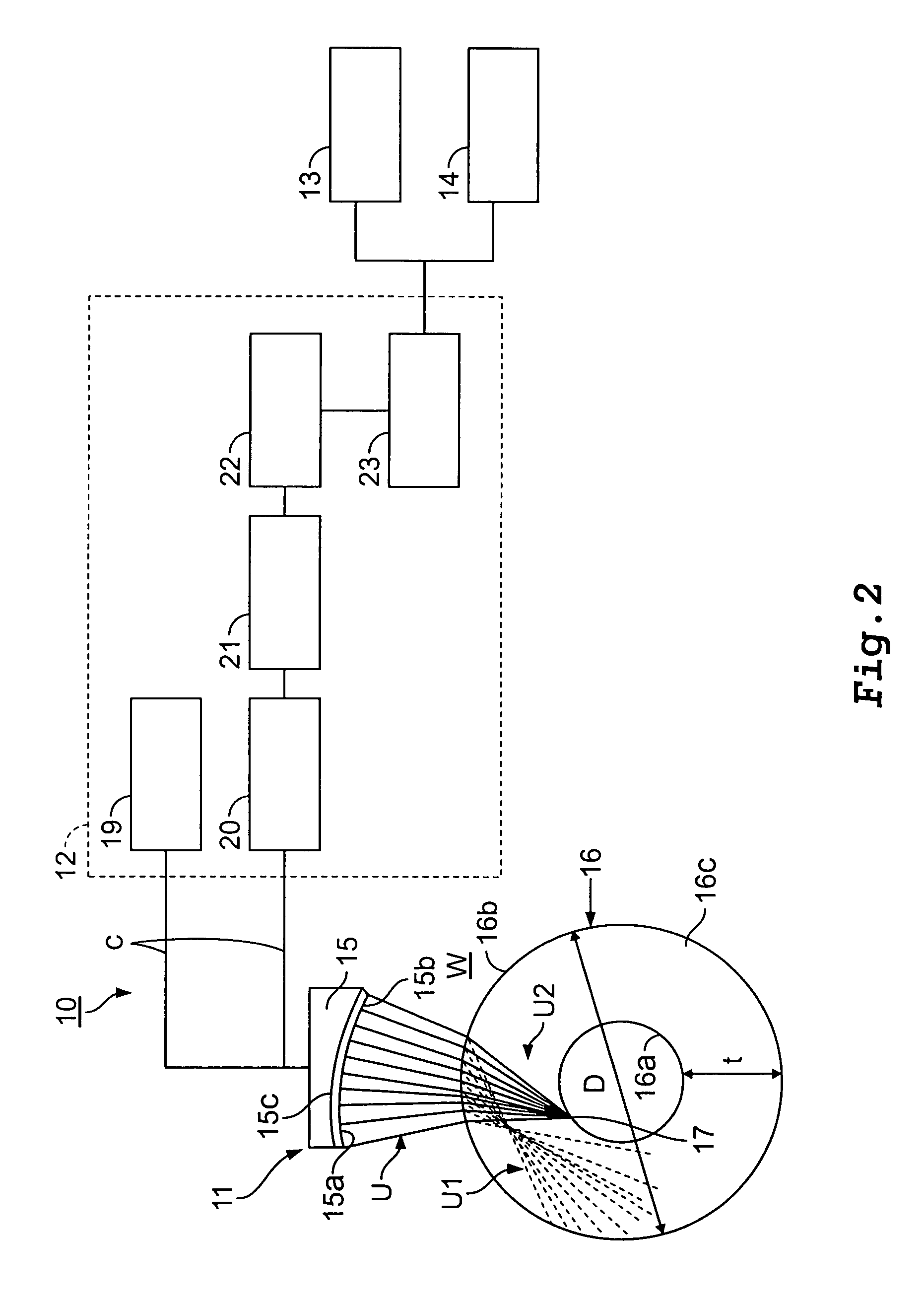
[0126]FIG. 2 is a block diagram schematically showing the structure of this embodiment of an ultrasonic flaw detection apparatus 10.

[0127]As shown in this figure, this embodiment of an ultrasonic flaw detection apparatus 10 has an ultrasonic probe 11, an ultrasonic flaw detector 12, an alarm 13, and a marking device 14. These will be explained in sequence.

[Ultrasonic Probe 11]

[0128]Like a conventional ultrasonic probe of this type, the ultrasonic probe 11 has a casing which houses a sound absorbing material, a tr...

second embodiment

[0178]FIG. 8 is an explanatory view schematically showing the structure of an ultrasonic flaw detection apparatus 30 of this embodiment.

[0179]As shown in FIG. 8, an ultrasonic flaw detection apparatus 30 according to this embodiment has two ultrasonic probes 32 each having a transducer 31, 31, an ultrasonic flaw detector (not shown), an alarm (not shown), and a marking device (not shown). The unillustrated ultrasonic flaw detector, alarm, and marking device have the same structure as in the above-described first embodiment, so an explanation thereof will be omitted.

[0180]This ultrasonic flaw detection apparatus 30 has probe holders 33, 33 which respectively hold transducers 31, 31, lower horizontal arms 34, 34 which respectively hold probe holders 33, 33, vertically movable arms 35, 35 which support the lower horizontal arms 34, 34 and are connected in the vertical direction with an upper horizontal arm 37, horizontally movable arms 36, 36 which are secured to the upper portion of t...

third embodiment

[0190]In this third embodiment, in contrast to the above-described first and second embodiments, the case will be explained in which the transducer is constituted by a plurality of oscillation-generating elements disposed side by side so as to have a planar shape.

[0191]FIG. 9 is a block diagram schematically showing the structure of an ultrasonic flaw detection apparatus 40 according to this embodiment. As shown in this figure, the ultrasonic flaw detection apparatus 40 according to this embodiment has an ultrasonic probe 42 equipped with a transducer 41, a transmission circuit 43, a receiving circuit 44, an alarm 45, and a marking device 46. The alarm 45 and the marking device 46 have the same structure as in the above-described first embodiment, so an explanation thereof will be omitted.

[0192]The transducer 41 constituting the ultrasonic probe 42 according to this embodiment is constituted by a plurality (such as 32) of minute piezoelectric elements 41a which oppose the outer surf...


PUM

PropertyMeasurementUnit
critical angleaaaaaaaaaa
sound velocityaaaaaaaaaa

Abstract

An ultrasonic probe performs flaw detection of a high (t / D) metal pipe. The front end portion of a transducer has at least a portion with an asymmetrically curved shape having a radius of curvature which progressively increases from one end towards the other end of the front end portion. The probe is disposed with respect to the pipe with its end having the smaller radius of curvature positioned on the side away from the direction of propagation of refracted waves, the end having a larger radius of curvature thereof positioned on the side in the direction of propagation of refracted waves. Angle beam flaw detection is carried out such that incident waves are generated which generate refracted longitudinal waves which do not reach the inner surface of the metal pipe and refracted transverse waves which are focused on the inner surface of the pipe.

Description

CROSS REFERENCE TO RELATED APPLICATION[0001]This application is a continuation of International Patent Application No. PCT / JP2006 / 307221, filed Apr. 5, 2006. This PCT application was not in English as published under PCT Article 21(2).TECHNICAL FIELD[0002]This invention relates to an ultrasonic probe, an ultrasonic flaw detection method, and an ultrasonic flaw detection apparatus. Specifically, the present invention relates to an ultrasonic probe, an ultrasonic flaw detection method, and an ultrasonic flaw detection apparatus which can detect minute flaws present in the outer surface, the inner surface, the interior and the like of a tubular metal body being inspected and particularly a metal pipe for which the ratio (t / D) of the wall thickness t with respect to the outer diameter D is at least 15%, for example, with certainty and with high precision by angle beam flaw detection.BACKGROUND ART[0003]A known nondestructive testing method for detecting flaws which are present in a tubu...

Claims


Application Information

Patent Timeline
Patent Type & Authority Patents(United States)
IPC IPC(8): G01N29/26
CPCG01N29/043G01N29/221G01N29/225G01N29/2487G01N2291/0421G01N2291/0422G01N2291/0428G01N2291/056G01N2291/106G01N2291/2634
Inventor YAMANO, MASAKI
Owner NIPPON STEEL CORP
Why Eureka
Try Eureka