Linear accelerator with wide bore CT scanner

a scanner and accelerator technology, applied in the field of radiation treatment, can solve the problems of increasing the potential for misdelivery, and reducing the effect of radiation dose on tumors

Inactive Publication Date: 2011-01-25
SIEMENS MEDICAL SOLUTIONS USA INC
View PDF10 Cites 23 Cited by
  • Summary
  • Abstract
  • Description
  • Claims
  • Application Information

AI Technical Summary

Benefits of technology

The claims are not limited to the disclosed embodiments, however, as those skilled in the art can readily adapt the teachings herein to create other embodiments and applications.

Problems solved by technology

If the relevant portions are not positioned exactly as required by the treatment plan, the goals of maximizing target radiation and minimizing healthy tissue radiation may not be achieved.
More specifically, errors in positioning the patient can cause the delivery of low radiation doses to tumors and high radiation doses to sensitive healthy tissue.
The potential for misdelivery increases with increased positioning errors.
Due to the foregoing, treatment plans are designed under the assumption that positioning errors may occur that may result in misdelivery of radiation.
Such compensation may decrease as margins of error in patient positioning decrease.

Method used


Image

  • Linear accelerator with wide bore CT scanner
  • Linear accelerator with wide bore CT scanner
  • Linear accelerator with wide bore CT scanner

Examples


Embodiment Construction

The following description is provided to enable a person in the art to make and use some embodiments and sets forth the best mode contemplated by the inventor for carrying out some embodiments. Various modifications, however, will remain readily apparent to those in the art.

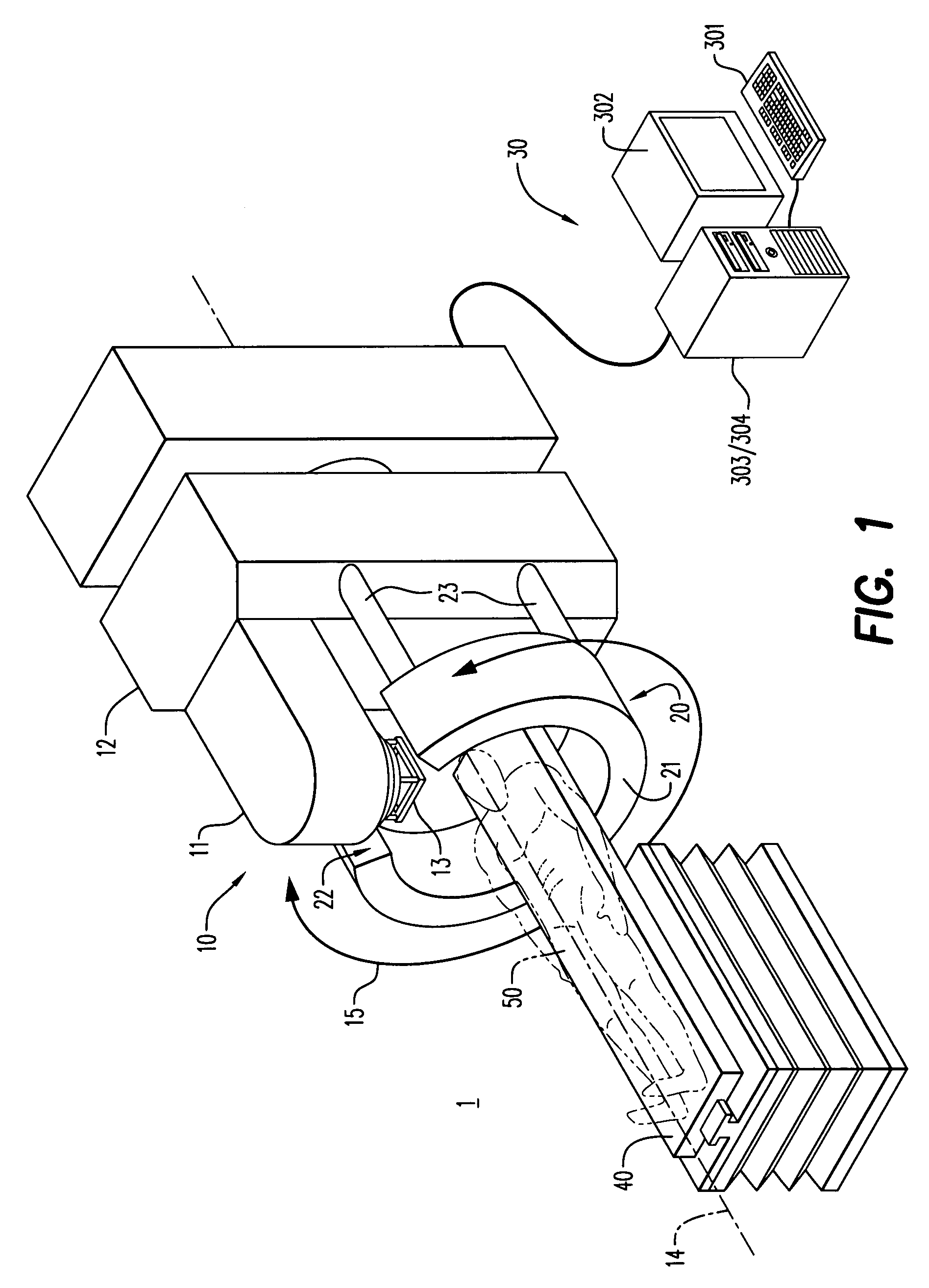
FIG. 1 illustrates radiation treatment room 1 pursuant to some embodiments. Radiation treatment room 1 includes linear accelerator (linac) 10, imaging system 20, operator console 30 and table 40. The elements of radiation treatment room 1 may be used to deliver radiation treatment to a target volume of beam object 50. In this regard, beam object 50 may comprise a patient positioned to receive radiation according to a radiation treatment plan. The elements of treatment room 1 may be employed in other applications according to some embodiments.

Linac 10 generates and emits the radiation, and is primarily composed of treatment head 11 and gantry 12. Treatment head 11 includes a beam-emitting device (not shown) for em...


PUM


Abstract

A system according to some embodiments may include a treatment head to emit a megavoltage radiation beam toward a volume, a plurality of X-ray sources to emit a respective kilovoltage radiation beam toward the volume while the plurality of X-ray sources are substantially stationary with respect to the volume, a detector to receive the plurality of kilovoltage radiation beams after having passed through the volume, and a processor to generate a three-dimensional image of the volume based only on the plurality of kilovoltage radiation beams received by the detector while the plurality of X-ray sources were substantially stationary with respect to the volume.

Description

BACKGROUND1. FieldThe embodiments described below relate generally to radiation treatment, and more particularly to imaging systems used in conjunction with such treatment.2. DescriptionAccording to conventional radiation treatment, a beam of treatment radiation is directed toward a tumor located within a patient. The radiation beam delivers a predetermined dose of therapeutic radiation to the tumor according to an established treatment plan. The delivered radiation kills cells of the tumor by causing ionizations within the cells.Treatment plans are therefore designed to maximize radiation delivered to a target while minimizing radiation delivered to healthy tissue. However, a treatment plan is designed assuming that relevant portions of a patient will be in a particular position relative to a treatment device during treatment. If the relevant portions are not positioned exactly as required by the treatment plan, the goals of maximizing target radiation and minimizing healthy tissue...

Claims


Application Information

Patent Timeline
Patent Type & Authority Patents(United States)
IPC IPC(8): A61N5/10
CPCA61B6/032A61B6/4014A61B6/466A61N5/1049A61B6/0457A61B6/4028A61B6/4488A61N2005/1061A61B6/0487
Inventor JEFFERY, ANDREW
Owner SIEMENS MEDICAL SOLUTIONS USA INC
Why Eureka
Try Eureka