Saddle riding type vehicle

a riding type, saddle technology, applied in the direction of cycle equipment, transportation and packaging, cycle, etc., can solve the problems of different wheelbases, engine output cannot be efficiently transmitted to the rear wheels, etc., to improve the transmission efficiency of engine output and improve maintainability

Inactive Publication Date: 2011-02-01
YAMAHA MOTOR CO LTD
View PDF6 Cites 8 Cited by
  • Summary
  • Abstract
  • Description
  • Claims
  • Application Information

AI Technical Summary

Benefits of technology

In view of the above, preferred embodiments of the present invention provide a saddle riding type vehicle which improves transmission efficiency of engine output while improving maintainability.
According to a preferred embodiment of the present invention, the pair of shaft drive mechanisms drive the pair of rear wheels through the differential mechanism. Thus, at times of making a turn, smooth turning movement is realized by absorbing a rotating speed difference between the pair of rear wheels. This construction can also solve the problem of maintenance which may occur with a construction using chains for drive transmission. The pair of rear wheels are independently supported by the pair of support mechanisms, and each shaft drive mechanism has a pair of constant velocity universal joints arranged in a positional relationship of point symmetry, with a coupling yoke located in a position coinciding with the pivot axis of the support mechanism. Therefore, even when the vehicle body is leaned and the rear wheel located inward greatly approaches the vehicle body, constant speed drive can be maintained to transmit engine drive to the rear wheels. As a result, the transmission efficiency of engine output can be improved.
Since drive is transmitted through the damper mechanisms, the drive can be transmitted smoothly to the rear wheels by inhibiting the influence of any variations occurring with the output of the engine. Further, stalling of the engine is prevented when its rotating speed falls momentarily due to the rear wheels riding on surface irregularities.
Then, compactness of the engine can be achieved while realizing smooth turning movement by absorbing a rotating speed difference between the pair of rear wheels.
Since the first transmission shaft includes the first bearing and the second transmission shaft includes the second bearing, wobbling of the first transmission shaft and second transmission shaft is prevented to reduce loss of the drive.

Problems solved by technology

Therefore, when tension of the chains is appropriately adjusted for the two rear wheels, there arises a problem of creating different wheelbases which are the distances between the two rear wheels and front wheel(s).
However, because of the positional relationship between the rear fork and universal joint, when the rear end of the rear fork moves very close to the vehicle body, more particularly, when the vehicle body sinks greatly relative to the rear fork or the rear fork flips up relative to the vehicle body, there arises a problem that the engine output cannot be transmitted to the rear wheels efficiently.

Method used


Image

  • Saddle riding type vehicle
  • Saddle riding type vehicle
  • Saddle riding type vehicle

Examples


Embodiment Construction

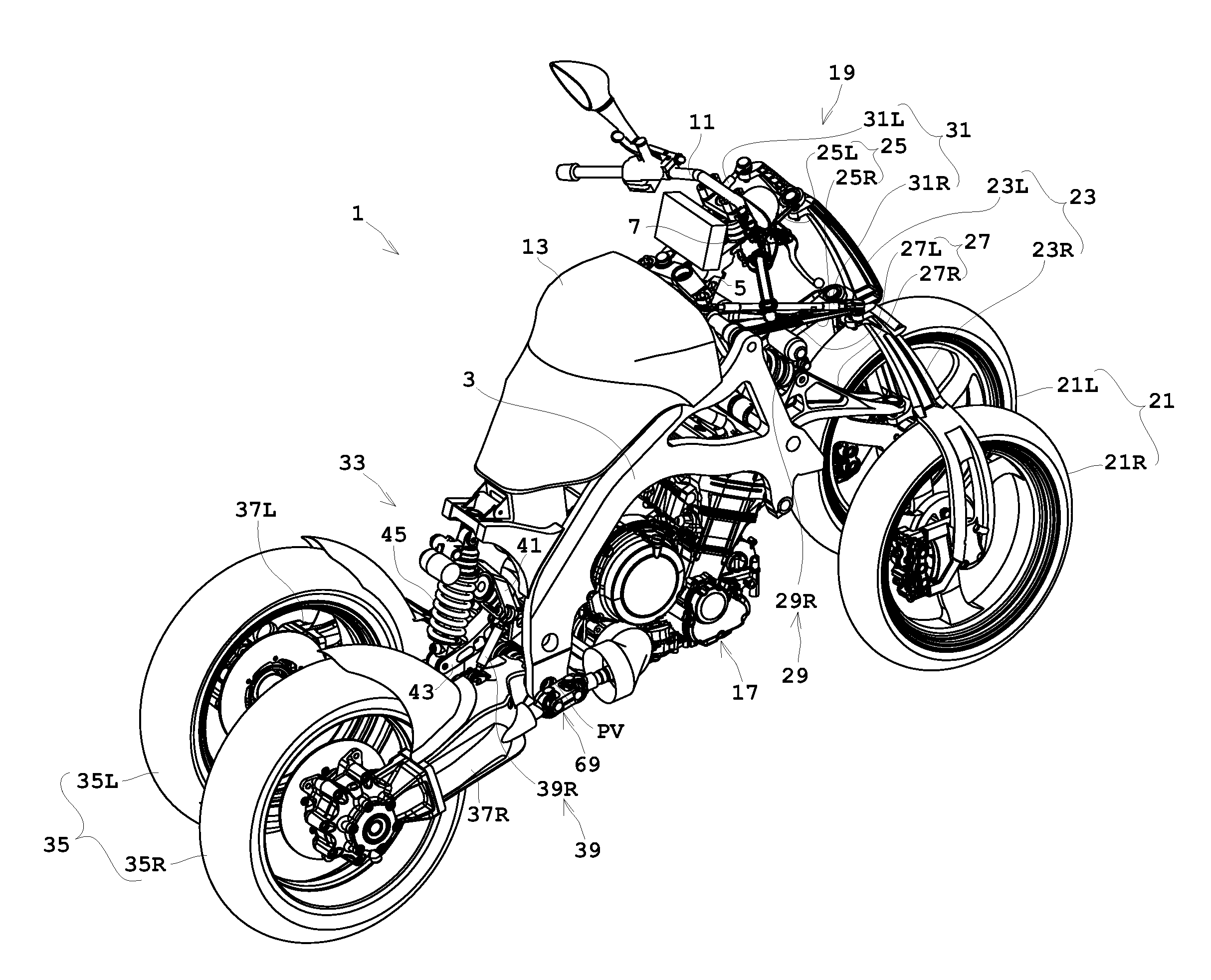
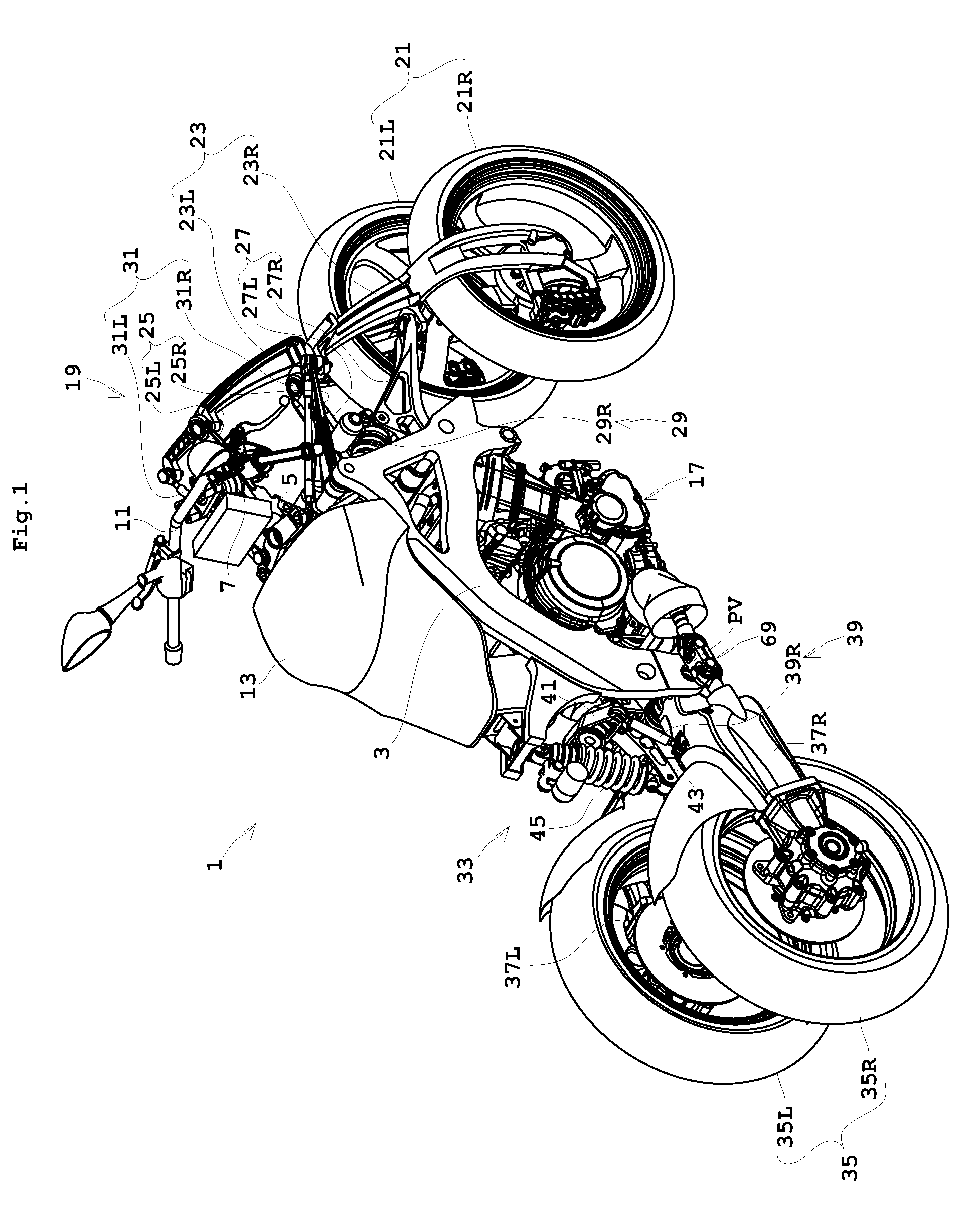
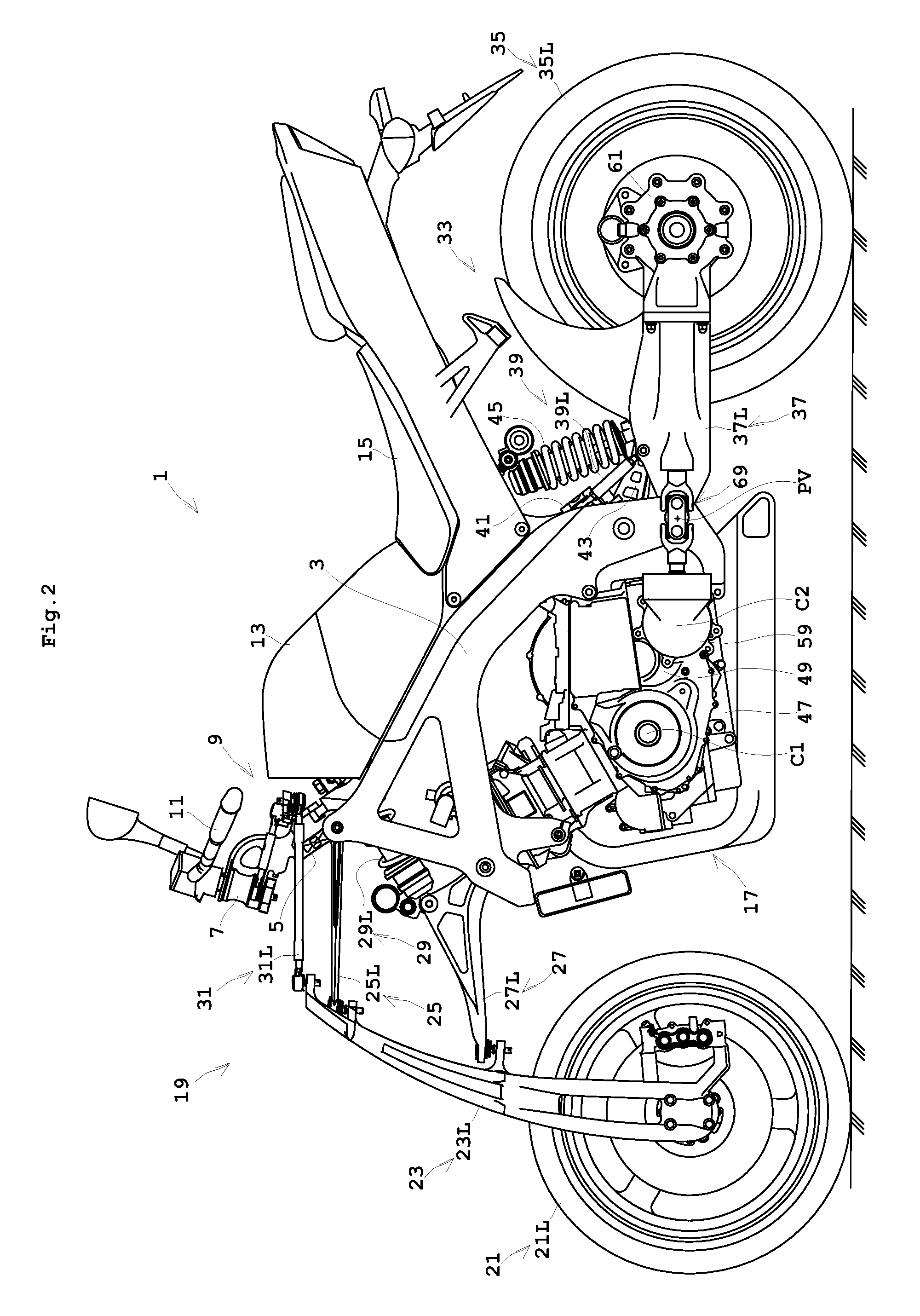
A saddle riding type vehicle according to preferred embodiments of the present invention will be described hereinafter with reference to the drawings.

FIG. 1 is a perspective view showing an outline construction of a saddle riding type vehicle according to a preferred embodiment of the present invention. FIG. 2 is a side view showing an outward appearance of the saddle riding type vehicle according to a preferred embodiment of the present invention. FIG. 3 is a rear view of the saddle riding type vehicle according to a preferred embodiment of the present. The seat illustrated in FIGS. 2 through 4, for example, is omitted from FIG. 1. FIG. 4 is a rear view of the saddle riding type vehicle in a leaning state. FIG. 5 is a view in cross section of the vehicle from an engine to rear wheels. The terms “right”, “left”, “front” and “rear” used in the following description to indicate directions refer to the right, left, front and rear seen from the rider seated on the saddle riding type veh...


PUM


Abstract

A saddle riding type vehicle capable of making turns by leaning a vehicle body includes a pair of rear wheels provided at opposite sides of the vehicle body, a pair of support mechanisms arranged to support the pair of rear wheels to be movable, independently of each other, up and down about a pivot axis relative to the vehicle body, an engine disposed forward of the pivot axis to produce a drive force, a differential mechanism arranged to distribute the drive force of the engine to the pair of rear wheels and to absorb a rotating speed difference between the pair of rear wheels at a time of making a turn, the differential mechanism including drive shafts arranged between the engine and the pivot axis, a pair of shaft drive mechanisms provided for the pair of rear wheels, respectively, and arranged to transmit the drive force of the differential mechanism to the pair of rear wheels, and a pair of constant velocity universal joints provided for the pair of shaft drive mechanisms, respectively, each including a pair of universal joints connected by a coupling yoke, the coupling yoke being located on the pivot axis, and the pair of universal joints being arranged in a positional relationship of point symmetry.

Description

BACKGROUND OF THE INVENTION1. Field of the InventionThe present invention relates to a saddle riding type vehicle such as a three-wheeled or four-wheeled automotive vehicle having a pair of wheels at least at a rear portion of a vehicle body, which can make turns by leaning the vehicle body.2. Description of the Related ArtConventionally, this type of vehicle includes a saddle riding type vehicle having two rear driven wheels, which can make turns by leaning a vehicle body. With such a vehicle, it is common practice to drive the two rear wheels with chains instead of driving only one of the rear wheels.Chains have a characteristic to become elongated through use. In order to assure proper drive, it is necessary to adjust tension of the chains by adjusting positions of the rear wheels. Although the chains of the two rear wheels are adjusted, the two chains usually are different in the degree of elongation. Therefore, when tension of the chains is appropriately adjusted for the two re...

Claims


Application Information

Patent Timeline
Patent Type & Authority Patents(United States)
IPC IPC(8): B60K17/00B60G3/04B62M17/00B62K5/00B62K5/01B62K5/02B62K25/24
CPCB60G3/145B60G3/207B60G21/007B60G21/05B62K5/01B62K5/10B62M17/00B60G2200/34B60G2200/42B60G2200/422B60G2200/44B60G2204/143B60G2204/148B60G2204/19B60G2204/414B60G2204/423B60G2204/82B60G2204/8302B60G2300/124B60G2300/45B62K2005/001
Inventor TSUJII, EIICHIROUHIRANO, MASAYUKITOYOTA, TAKESHIHASEGAWA, SACHIYOFUJII, ISAO
Owner YAMAHA MOTOR CO LTD
Why Eureka
Try Eureka