
Cooled RF ablation needle

a technology of rf and needle, which is applied in the field of new electrosurgical instruments, can solve the problems of destroying adjacent tissue, heating and destroying adjacent tissue, and the size of rf lesions for a given electrode geometry is generally considered to be somewhat limited, so as to prevent tissue ablation

Inactive Publication Date: 2011-02-01
COVIDIEN AG
View PDF177 Cites 29 Cited by
  • Summary
  • Abstract
  • Description
  • Claims
  • Application Information

AI Technical Summary

Benefits of technology

The present patent relates to novel electrosurgical instruments for tissue ablation, systems for tissue ablation, and methods for ablating tissues containing abnormalities such as cancerous tumors. The ablation instruments include an ablation electrode assembly with a hub, at least one electrically conductive ablation needle extending from the hub, and a heat sink operatively connected to the ablation needle. The heat sink can be in conductive engagement with the distal end portion of the ablation needle to draw energy away from the tissue. The ablation needle can have a cavity therein where the heat sink is placed. The ablation electrode assembly can also include an outlet conduit for delivering fluid into the chamber of the hub. The method involves using the ablation electrode assembly to ablate tissue in a patient. The technical effects include improved ablation of tissues with reduced risk of complications and improved outcomes for patients with abnormalities such as cancer.

Problems solved by technology

Typically, the current density is very high near the tip of the ablation electrode, which heats and destroys the adjacent tissue.
Consequently, the lesion size for a given electrode geometry generally has been considered to be somewhat limited by the fact that the tissue near the tip must not exceed 100° C.
As an attendant consequence, the size of RF lesions for a given electrode geometry have been somewhat limited.
However, such systems, in requiring multiple tissue punctures, increase trauma to the patient.

Method used


Image

  • Cooled RF ablation needle
  • Cooled RF ablation needle
  • Cooled RF ablation needle

Examples


Embodiment Construction

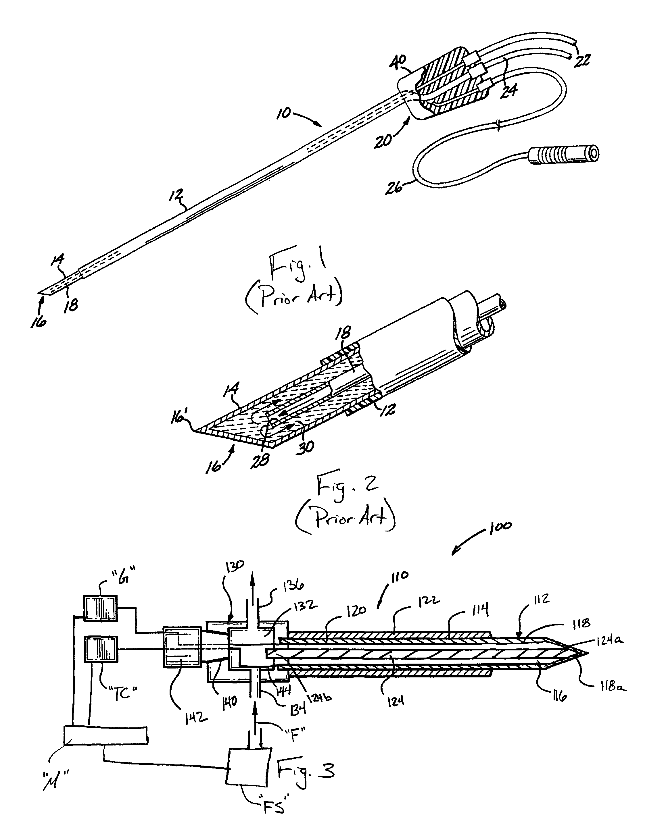
[0049]Referring initially to FIGS. 1 and 2, a prior art needle electrode according is shown and described and is generally designated as 10. As seen in FIG. 1, needle electrode 10 includes a distal end 16 and a proximal end 20 and further includes an outer tube 14 having a tip part 16 which is exposed and a tip point 16′ (see FIG. 2) which is construed so as to penetrate tissue with a minimum risk of hemorrhage from the puncture tract. The non-exposed part of the outer tube 14 is surrounded by an insulating material 12. A distal portion of outer tube 14 is non-insulated and thereby exposed for DC or AC, preferably RF delivery. An inner tube 18 is provided inside the tube 14 co-axially with the outer tube 14.

[0050]An adapter 40 is provided at the proximal end 20 of needle electrode 10, opposite the tip part or distal end 16. The adapter 40 is equipped with a line 22, the line 22 being connected to the inner tube 18 and communicating therewith for providing a cooling fluid, such as wa...


PUM


Abstract

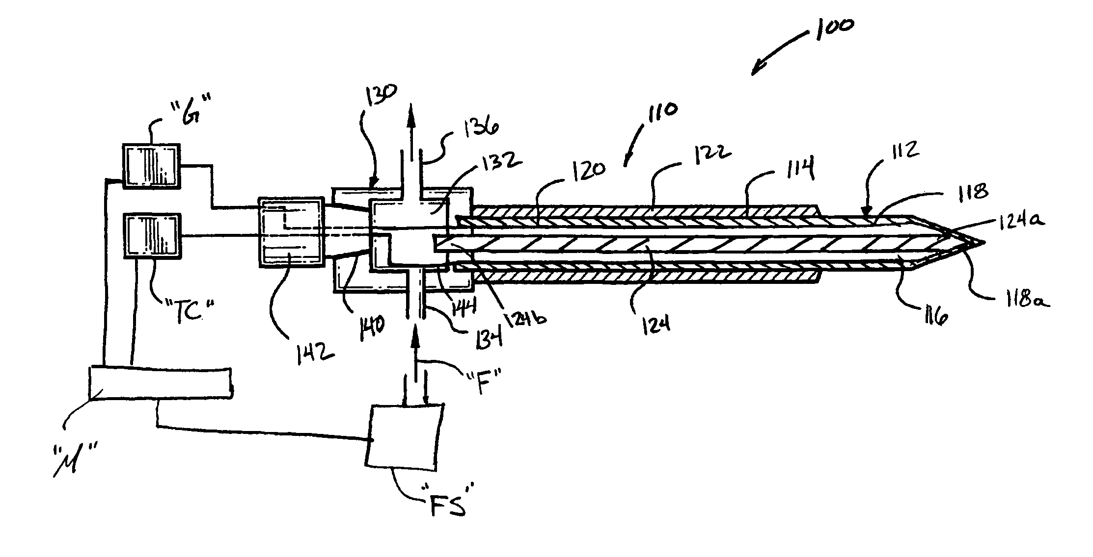
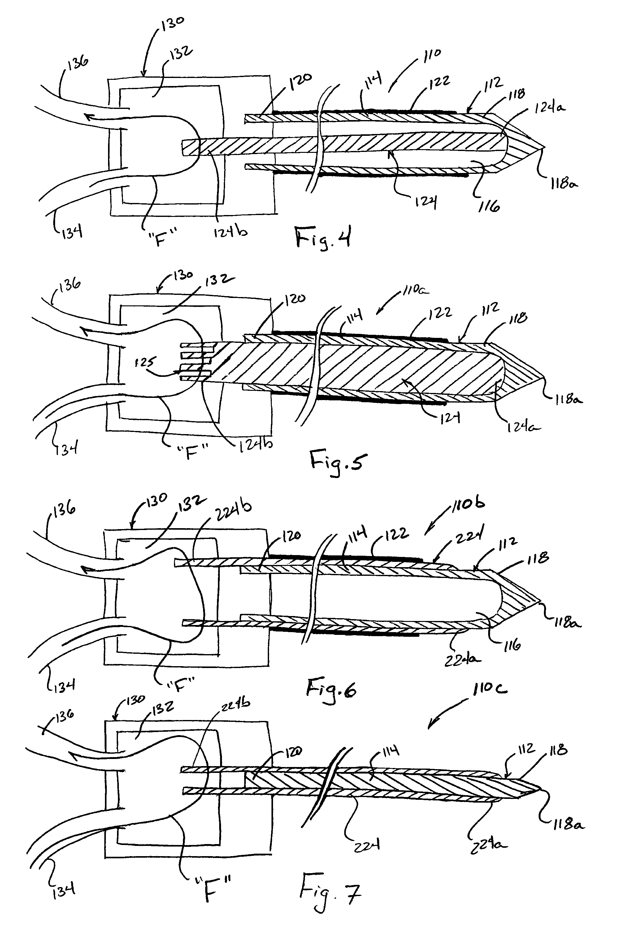
An ablation system includes an ablation electrode assembly operatively connectable to sources of electrosurgical energy and cooling fluid. The electrode assembly includes a hub defining a chamber therein; at least one electrically conductive ablation needle extending from the hub, the ablation needle including a distal end portion configured to penetrate tissue, said distal end portion being electrically and thermally conductive for establishing electric and thermal communication with the tissue; a heat sink operatively connected to the ablation needle, the heat sink being connected to the ablation needle to draw energy away from at least the distal end portion thereof, the heat sink including a proximal end extending into the chamber of the hub; and a conduit fluidly connected to the hub for delivering fluid into the chamber thereof from the source of fluid, wherein the fluid withdraws energy from the proximal end of the heat sink.

Description

BACKGROUND[0001]1. Technical Field[0002]The present disclosure relates to advances in medical systems and procedures for prolonging and improving human life and, more particularly, to novel electrosurgical instruments for tissue ablation, systems for tissue ablation including the electrosurgical instruments, and methods for ablating tissues containing abnormalities such as cancerous tumors using the systems for tissue ablation.[0003]2. Discussion of Related Art[0004]Therapeutic lesions in living bodies have been accomplished for many decades using radio-frequency (RF) and other forms of energy. The procedures have been particularly useful in the field of neurosurgery, typically where RF-ablation electrodes (usually of elongated cylindrical geometry) are inserted into a living body. A typical form of such ablation electrodes incorporates an insulated sheath from which an exposed (uninsulated) tip extends.[0005]Generally, the ablation electrode is coupled between a grounded RF power s...

Claims


Application Information

Patent Timeline
Patent Type & Authority Patents(United States)
IPC IPC(8): A61B18/14
CPCA61B18/1477A61B2018/00005A61B2018/00023A61B2018/143
Inventor PETERSON, DARION
Owner COVIDIEN AG
Learn More