Power supply control for power generator

a power generator and power supply technology, applied in emergency power supply arrangements, dc-ac conversion without reversal, transportation and packaging, etc., can solve the problems of insufficient power from one fuel cell to satisfy the electrical load requirements of applications, instantaneous start and stop generating electricity, etc., and achieve the effect of loss of efficiency

Active Publication Date: 2011-02-01
CERES INTPROP CO LTD
View PDF15 Cites 199 Cited by
  • Summary
  • Abstract
  • Description
  • Claims
  • Application Information

AI Technical Summary

Benefits of technology

[0012]In embodiments of the invention, the system includes a voltage regulated D.C. bus connected between a D.C. to D.C. converter and a bi-directional inverter, the bi-directional inverter also being connected to an A.C. grid, and the D.C. to D.C. converter also being connected to at least one fuel cell, wherein at least one D.C. auxiliary load of the at least one fuel cell is connected to the voltage regulated D.C. bus. The system can therefore be made significantly smaller, and lighter, at the expense of a slight loss of efficiency.
[0013]By providing D.C. auxiliary load(s) of the at least one fuel cell on the D.C. bus, transformation of the at least one fuel cell generated current from D.C. to mains A.C. and back to D.C. to power the auxiliary loads is avoided. In this way, a single conversion stage only is required to provide the power to the D.C. load, whether it be from the at least one fuel cell, or from the A.C. grid.

Problems solved by technology

In general, the power from one fuel cell is insufficient to satisfy the electrical load requirements of the applications that fuel cells are provided for.
Due to their nature of operation, requiring fuel and air to be provided to the fuel cell under the right conditions of temperature, and in some cases pressure, fuel cell systems do not instantaneously start and stop generating electricity.

Method used


Image

  • Power supply control for power generator
  • Power supply control for power generator
  • Power supply control for power generator

Examples


first embodiment

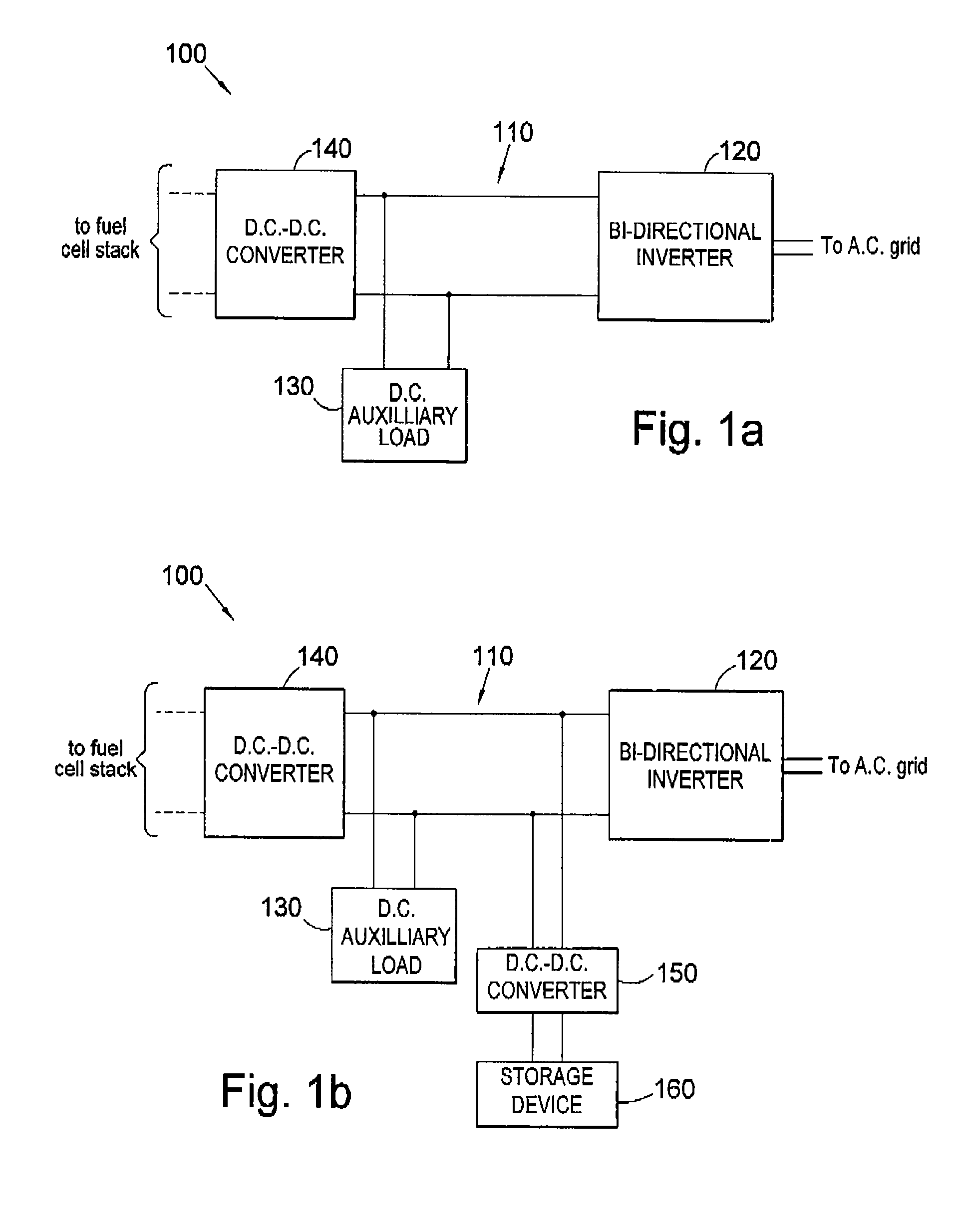
[0033]FIG. 1b shows a variation of the control system according to the In this variation, like components are referred to with like reference numerals. In this variation, which otherwise corresponds to that discussed above in relation to FIG. 1a, a further D.C.:D.C. converter 150 is provided, which is connected to the voltage regulated D.C. bus 110. An electrical energy storage device 160 is connected to the D.C. bus 110 via the further D.C.:D.C. converter 150. In the present embodiment, the storage device is a battery system. However, other storage devices could include capacitors, flywheels or others as would be known to one skilled in the art.

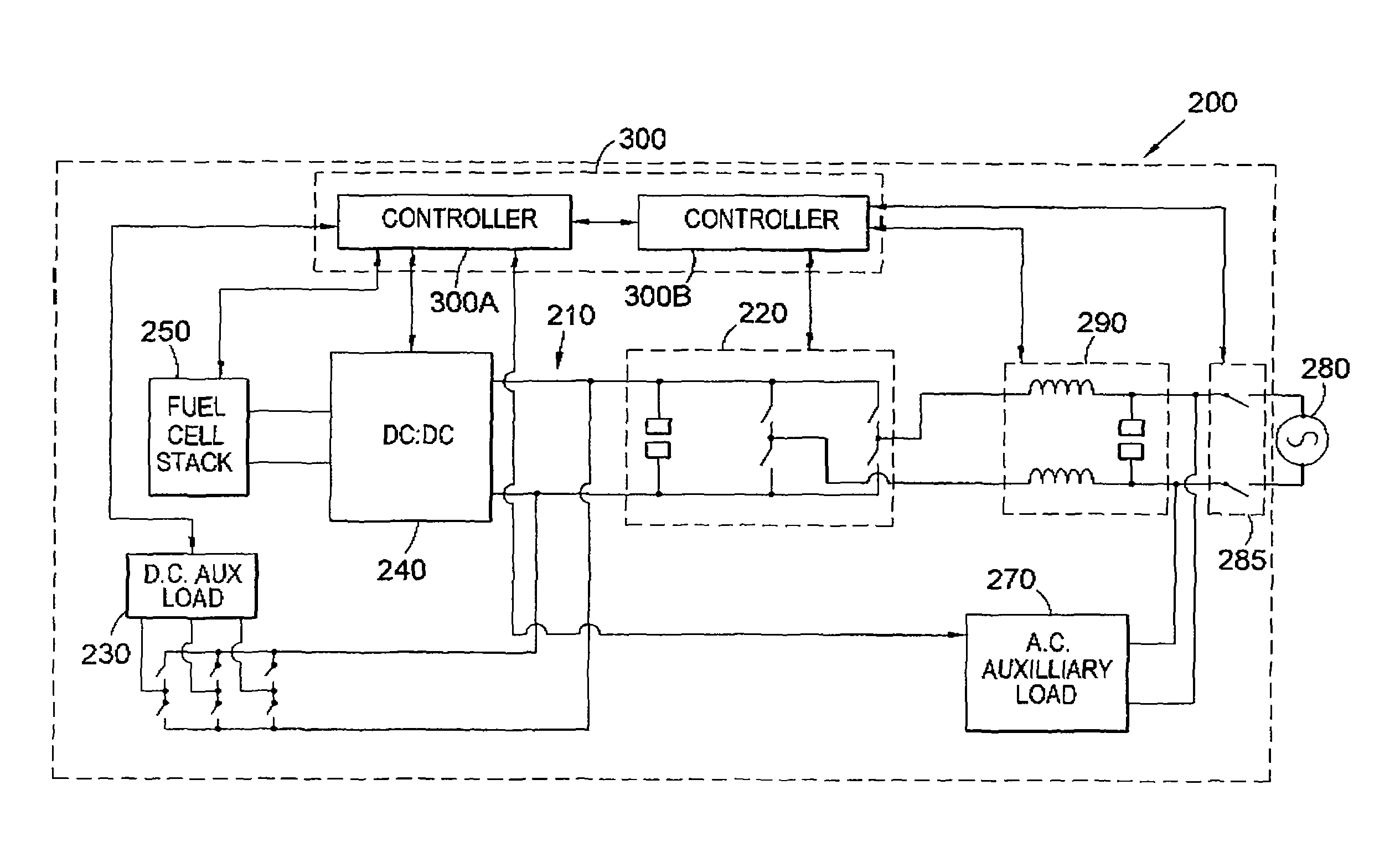
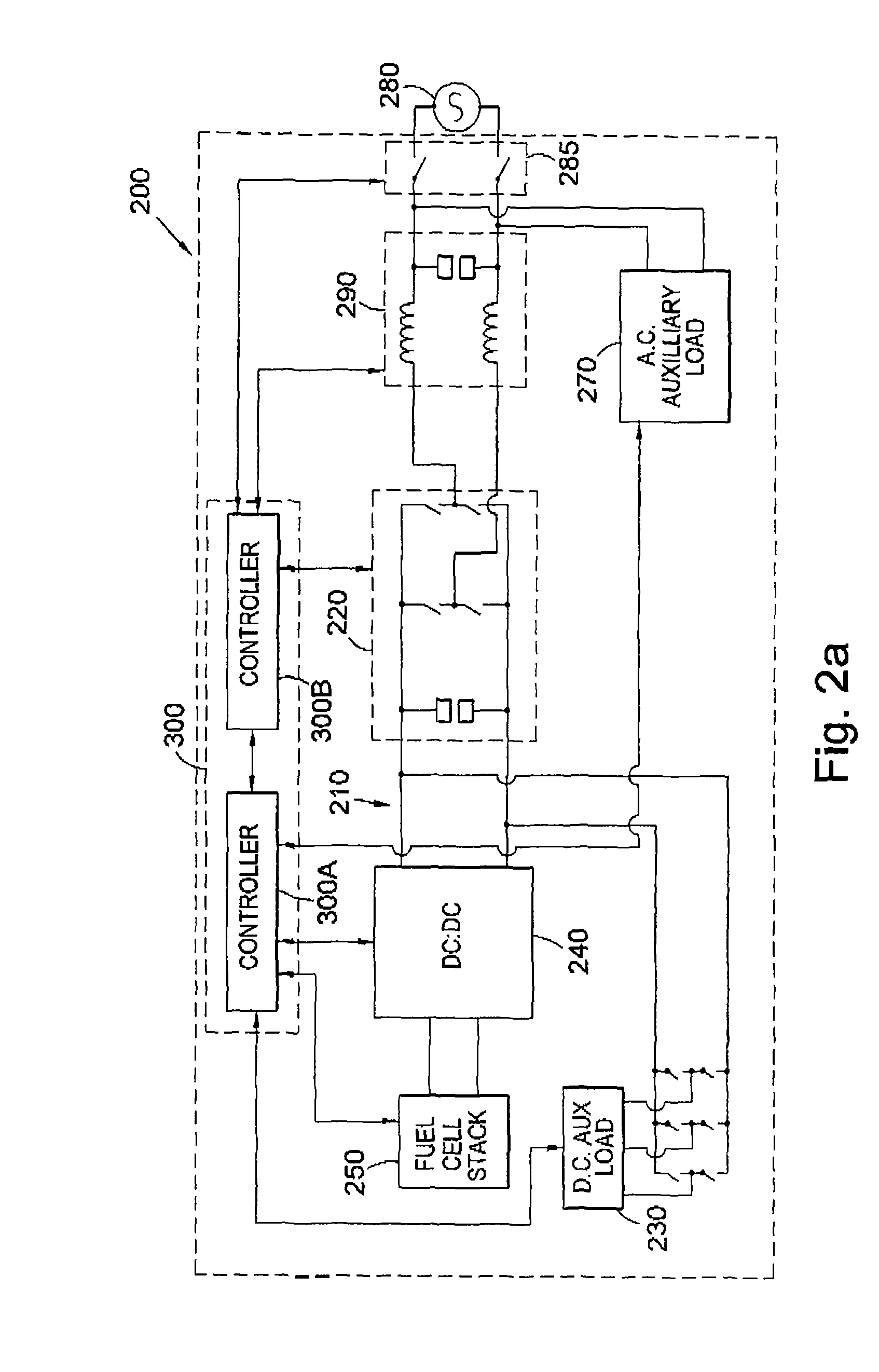
[0034]FIG. 2a shows a second embodiment of the invention. The second embodiment is similar to the first embodiment, and shares the features shown in the first embodiment. Therefore, a D.C. bus 210 is provided, which is voltage regulated by a bidirectional inverter 220. In the present embodiment, the bidirectional inverter 220 is shown in a ...

second embodiment

[0039]FIGS. 2b and 2c show two variations of the Like components between the figures are referred to by like reference numerals. The variation shown in FIG. 2b corresponds to that shown in FIG. 2a, with the exception that a D.C.: D.C. converter 310 is connected to the D.C. bus 210. An electrical energy storage device 320 is connected to the D.C. bus 210 via the D.C.:D.C. converter 310. The D.C.:D.C. converter 310 also includes a controller, to control the energy transfer between the storage device 320 and the D.C. bus 210. The controller in the D.C.:D.C. converter 310 is coupled to the controller 300.

[0040]FIG. 2c shows a variation on the second embodiment in which a D.C.:D.C. converter 310a is provided, coupled to the D.C. bus 210, and also coupled to a further D.C. bus 410, external to the system 200. One or more D.C. storage devices 320a are connected to the further D.C. bus 410. Additionally, or alternatively, one or more further fuel cell systems may be connected to the furthe...


PUM


Abstract

A system (100) for connecting a fuel cell stack to an A.C. grid to provide power thereto is disclosed in which a voltage regulated D.C. bus (110) is provided to be coupled to the fuel cell stack, a bidirectional inverter (120) is coupled to the D.C. bus (110), and is to be coupled between the D.C. bus (110) and the A.C. grid. At least one D.C. auxiliary load (130) of the fuel cell stack is provided coupled to the D.C. bus (110). A D.C. to D.C. converter (140) is provided between the fuel cell stack and the D.C. bus (110).

Description

CROSS-REFERENCE TO RELATED APPLICATION[0001]This application claims the benefit of U.S. Provisional Application No. 60 / 854,081 filed Oct. 25, 2006.[0002]The present invention relates to power generation. In particular, the present invention relates to systems for controlling the connection of a fuel cell stack and an A.C. grid.BACKGROUND OF THE INVENTION[0003]Fuel cells can be a useful, efficient and environmentally friendly solution to power generation. They have few moving parts, and are highly efficient at converting energy contained in the fuel into usable electricity, and, in some cases, useable heat. Fuel cells generate direct current (D.C.). Generally, a fuel cell will generate D.C. at a voltage in the order of 1V, and, when operating under load, between 0.3V and 0.8V. The voltage changes, depending on the operating parameters of the fuel cells and the load drawn.[0004]In general, the power from one fuel cell is insufficient to satisfy the electrical load requirements of the ...

Claims


Application Information

Patent Timeline
Patent Type & Authority Patents(United States)
IPC IPC(8): H02J7/00H02J9/00
CPCH02J3/387H02M7/797H02J5/00H02J2001/004H02J2300/30H02J3/381H02M7/5387H02M7/68H02M7/48
Inventor EVANS, CHRISTOPHER JOHNELLIOTT, CHARLES RICHARDWATKINS, STEPHEN JAMES
Owner CERES INTPROP CO LTD
Why Eureka
Try Eureka