Tilt lens system and image pickup apparatus

a technology of tilt lens and image pickup, which is applied in the field of new tilt lens system and image pickup apparatus, can solve the problems of incorrect operation of ae, difficulty in mechanical interlocking, and inability to properly operate a

Inactive Publication Date: 2011-02-01
SONY CORP
View PDF7 Cites 10 Cited by
  • Summary
  • Abstract
  • Description
  • Claims
  • Application Information

AI Technical Summary

Benefits of technology

[0017]Accordingly, it is desirable to provide a tilt lens system and an image pickup apparatus having the tilt lens system. The tilt lens system does not have a shift function which can be performed by the photo retouch software as mentioned above. In the tilt lens system, while elements relating to AF and AE are arranged constantly on the primary optical axis, only a partial lens unit is tilted to enable photographing satisfying the Scheimpflug rule; and not only in a normal use condition, but also during tilting, AF and AE can be used, to realize an easy operation of photographing with tilting, and to markedly reduce a variation in aberration.
[0020]With the invention, by tilting the partial lens unit, photographing satisfying the Scheimpflug rule can be provided. Also, AF and AE can be used not only in a normal use condition, but also during tilting; thereby an operation of photographing with tilting can be easily performed.

Problems solved by technology

However, when the perspective control is performed, the center of an exit pupil may be deviated from the center of a screen, or the exit pupil may be tilted during tilting.
Accordingly, AE may not be correctly operated.
If diaphragm blades are deviated from the optical axis due to the perspective control, or tilted together with the optical axis, the mechanical interlock may be extremely difficult.
Accordingly, AE may be incorrectly operated unless the aperture of the diaphragm is the open aperture, even when the perspective control is not performed.
However, such a lens may have bottlenecks.
In addition, the user has to operate the preset diaphragm, which is difficult to use.
Further, to perform the tilt control, troublesome operations, including manually focusing on an object, tilting to be aligned with the tilt of the object, thereby the object being defocused, manually focusing on the object again, and tilting again, have to be repeated to adjust the focus and the tilt angle to be optimum.
This is extremely difficult to use.
Therefore, the related arts assume that the problem during tilting of the partial lens unit is the movement of the center image.
However, the major problem during tilting of the partial lens unit is performance degradation caused by unbalanced aberration compensation when the condition of the optical system is continuously changed from a coaxial optical system to a decentered optical system.
It is desired to maintain the focusing performance in the whole optical system even with the unbalanced aberration compensation; however, the related arts do not disclose configurations or numerical examples to overcome such problems.
Therefore, the related arts could not provide a useful tilt lens system.

Method used


Image

  • Tilt lens system and image pickup apparatus
  • Tilt lens system and image pickup apparatus
  • Tilt lens system and image pickup apparatus

Examples


first embodiment

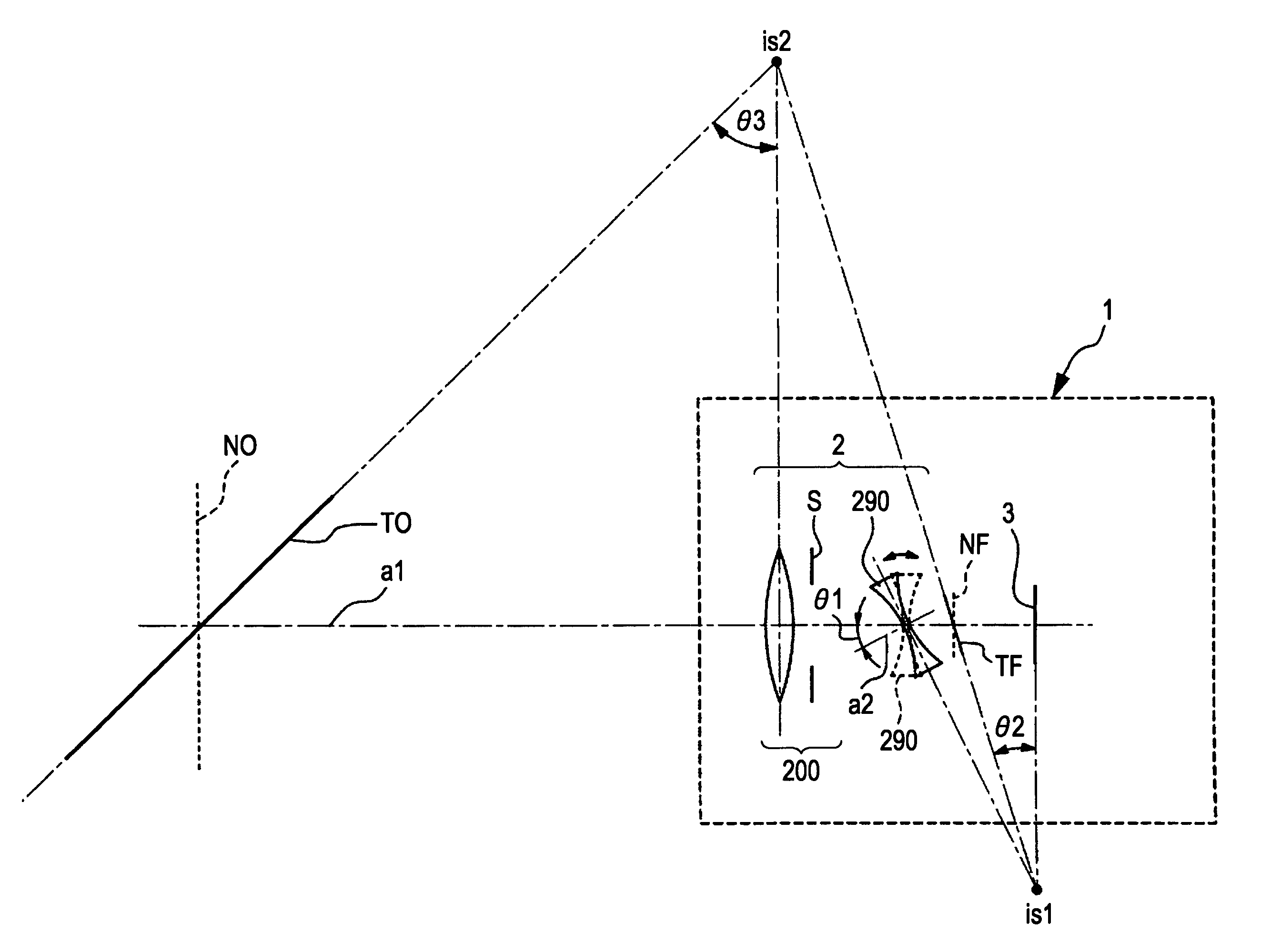
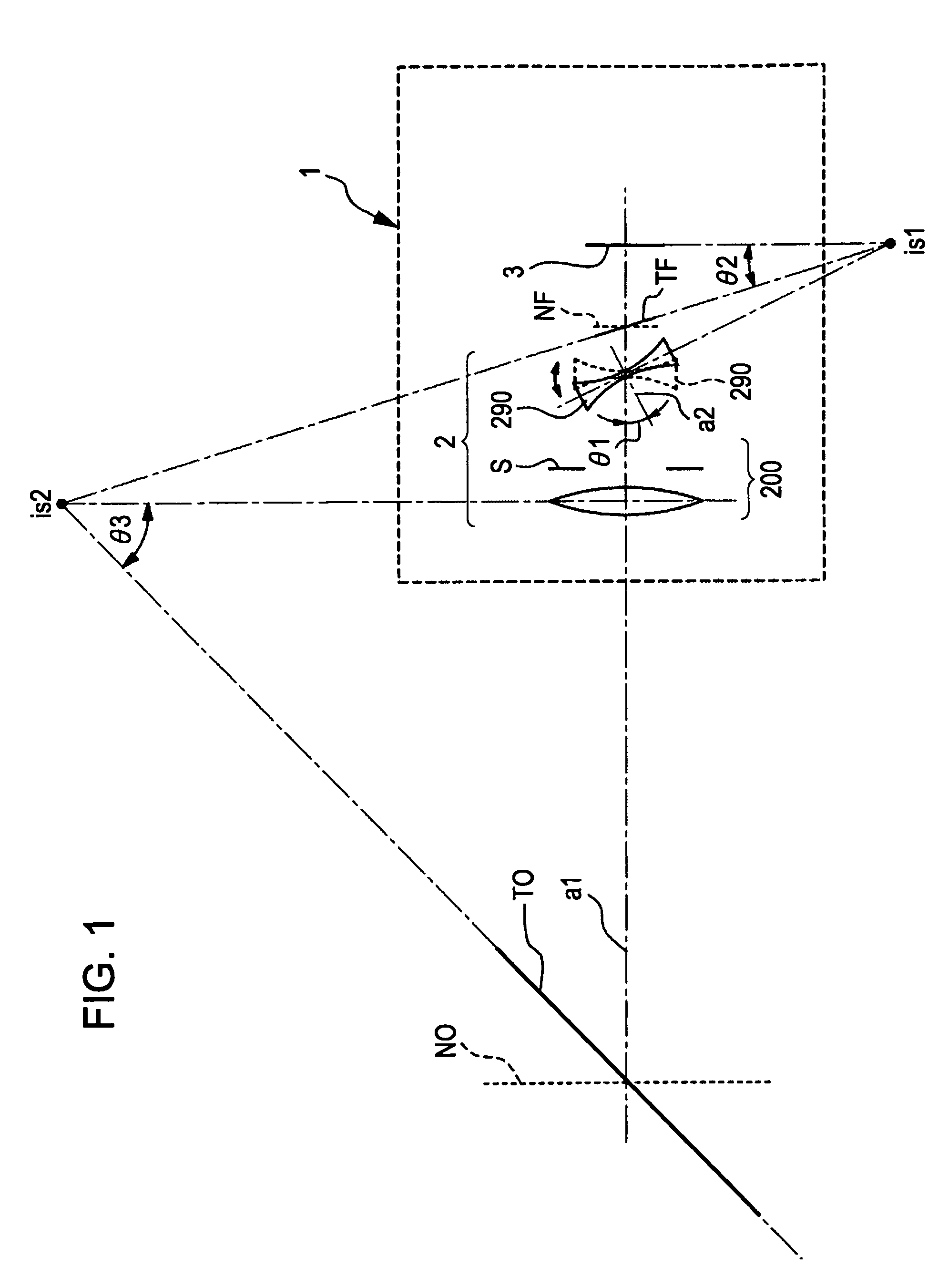
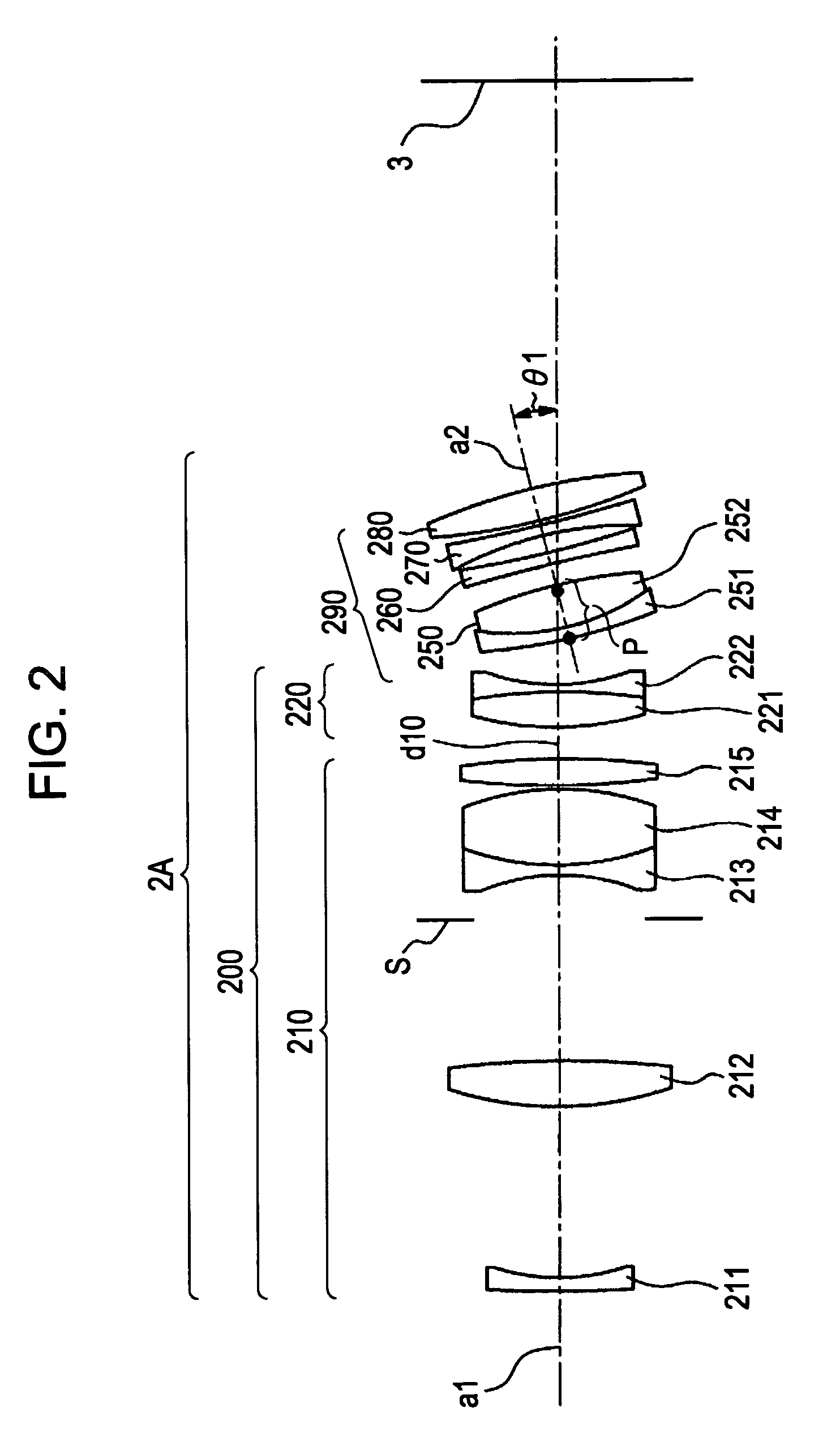
[0086]FIG. 2 is a cross section showing a lens arrangement of a tilt lens system 2A according to the invention. The tilt lens system 2A includes a master lens system 200, and a tilt lens unit 290, in order from the object side. The master lens system 200 has an optical axis (primary optical axis) a1. The tilt lens unit 290 has a negative refractive power, and has an optical axis a2. The optical axis a2 of the tilt lens unit 290 may be tilted with respect to the optical axis a1 of the master lens system 200. When the optical axis a2 of the tilt lens unit 290 is not tilted, the optical axis a2 is aligned with the optical axis a1 of the master lens system 200, thereby defining a coaxial optical system. The master lens system 200 includes a focus lens unit 210 and a fixed lens unit 220, in order from the object side.

[0087]The focus lens unit 210 includes a negative meniscus lens 211 having a concave surface with a larger curvature on the image side, a biconvex lens 212, a diaphragm S, a...

second embodiment

[0097]FIG. 8 is a cross section showing a lens arrangement of a tilt lens system 2B according to the invention. The master lens system 200 has an optical axis (primary optical axis) a1. The tilt lens system 2B includes a master lens system 200, and a tilt lens unit 290, in order from the object side. The tilt lens unit 290 has a negative refractive power, and has an optical axis a2. The optical axis a2 of the tilt lens unit 290 may be tilted with respect to the optical axis a1 of the master lens system 200. When the optical axis a2 of the tilt lens unit 290 is not tilted, the optical axis a2 is aligned with the optical axis a1 of the master lens system 200, thereby defining a coaxial optical system. The master lens system 200 includes a focus lens unit 210 and a fixed lens unit 220, in order from the object side.

[0098]The focus lens unit 210 includes a negative meniscus lens 211 having a concave surface with a larger curvature on the image side, a biconvex lens 212, a diaphragm S, a...

third embodiment

[0109]FIG. 14 is a cross section showing a lens arrangement of a tilt lens system 2C according to the invention. The tilt lens system 2C includes a master lens system 200, and a tilt lens unit 290, in order from the object side. The master lens system 200 has an optical axis (primary optical axis) a1. The tilt lens unit 290 has a negative refractive power, and has an optical axis a2. The optical axis a2 of the tilt lens unit 290 may be tilted with respect to the optical axis a1 of the master lens system 200. When the optical axis a2 of the tilt lens unit 290 is not tilted, the optical axis a2 is aligned with the optical axis a1 of the master lens system 200, thereby defining a coaxial optical system. The master lens system 200 includes a focus lens unit 210 and a fixed lens unit 220, in order from the object side.

[0110]The focus lens unit 210 includes a negative meniscus lens 211 having a concave surface with a larger curvature on the image side, a biconvex lens 212, a diaphragm S, ...


PUM


Abstract

A tilt lens system includes a focus lens unit movable during focusing; a diaphragm sharing a primary optical axis with the focus lens unit; and a tilt lens unit, arranged on an image side of the focus lens unit and the diaphragm, having a negative refractive power and an optical axis tiltable with respect to the primary optical axis. Conditional Expressions (1) and (2) are satisfied as follows,1.3<βt<1.7  (1)0<P<H1  (2)where βt is a lateral magnification of the tilt lens unit in a not tilted state, P is a distance from a most object side surface of the tilt lens unit to a rotating center of the tilt lens unit in a tilted state, and H1 is a distance from the most object side surface of the tilt lens unit to a first principal point of the tilt lens unit.

Description

CROSS REFERENCES TO RELATED APPLICATIONS[0001]The present invention contains subject matter related to Japanese Patent. Application JP 2007-157285 filed in the Japanese Patent Office on Jun. 14, 2007, the entire contents of which are incorporated herein by reference.BACKGROUND OF THE INVENTION[0002]1. Field of the Invention[0003]The present invention relates to new tilt lens systems and image pickup apparatuses. More particularly, the present invention relates to a tilt lens system, and an image pickup apparatus having the tilt lens system, for a video camera, a digital camera, or a digital camera or a film camera of single-lens reflex type. The tilt lens system has a tilt function, capable of focusing on not only an object arranged in parallel to an image pickup surface, but also an object arranged in a tilted manner with respect to the image pickup surface, without degrading an autofocus function and an exposure measurement function.[0004]2. Description of the Related Art[0005]In ...

Claims


Application Information

Patent Timeline
Patent Type & Authority Patents(United States)
IPC IPC(8): H04N5/225G03B13/00G02B27/64G02B13/10
CPCG02B13/00G03B5/06H04N5/2259G02B9/00G02B15/06
Inventor NANJO, YUSUKESUEYOSHI, MASAFUMI
Owner SONY CORP
Why Eureka
Try Eureka