
Methods for performing transient flow prediction and verification using discharge coefficients

a technology of discharge coefficient and transient flow, applied in the direction of fluid tightness measurement, instruments, water supply installation, etc., can solve the problems of mfc performance degrade, translation corresponding results may have errors, and substandard devices and/or defective devices

Active Publication Date: 2011-02-01
LAM RES CORP
View PDF22 Cites 24 Cited by
  • Summary
  • Abstract
  • Description
  • Claims
  • Application Information

AI Technical Summary

Problems solved by technology

Thus, inaccurate parameters may result in substandard device and / or defective device.
However, the translated corresponding results may have errors since the conversion factors have an inherent level of uncertainty.
Over time, the MFC performance may degrade resulting in a flow rate inaccuracy.
In addition to the ROR procedure being a lengthy process, the ROR procedure may also suffered from inaccuracy in matching process results from chamber to chamber.
In an example, large temperature difference in the chamber may result in a change in volume.
Thus, the ROR procedure is a cumbersome method that may introduce longer time duration due to elevated reaction chamber operation temperature.
As a result, the ROR procedure may contribute to cost of ownership without really providing a true method for validating the indicated flow rate of the MFC.
As a result, the eternal flow measurement device method is unable to test for the effect on flow rate due to the compressibility of the gases.
In addition, the smaller chamber ROR device usually requires the utilization of a separate proprietary computer system, thereby not providing an integrated solution with the plasma processing system.

Method used


Image

  • Methods for performing transient flow prediction and verification using discharge coefficients
  • Methods for performing transient flow prediction and verification using discharge coefficients
  • Methods for performing transient flow prediction and verification using discharge coefficients

Examples


Embodiment Construction

[0023]The present invention will now be described in detail with reference to various embodiments thereof as illustrated in the accompanying drawings. In the following description, numerous specific details are set forth in order to provide a thorough understanding of the present invention. It will be apparent, however, to one skilled in the art, that the present invention may be practiced without some or all of these specific details. In other instances, well known process steps and / or structures have not been described in detail in order to not unnecessarily obscure the present invention.

[0024]Various embodiments are described herein below, including methods and techniques. It should be kept in mind that the invention might also cover an article of manufacture that includes a computer readable medium on which computer-readable instructions for carrying out embodiments of the inventive technique are stored. The computer readable medium may include, for example, semiconductor, magne...


PUM


Abstract

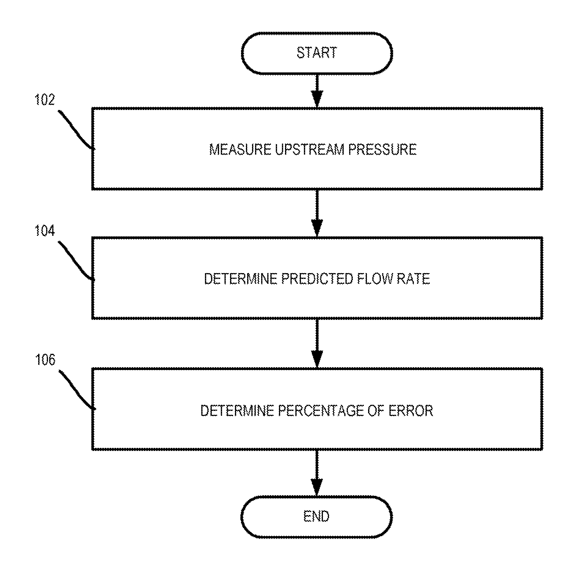
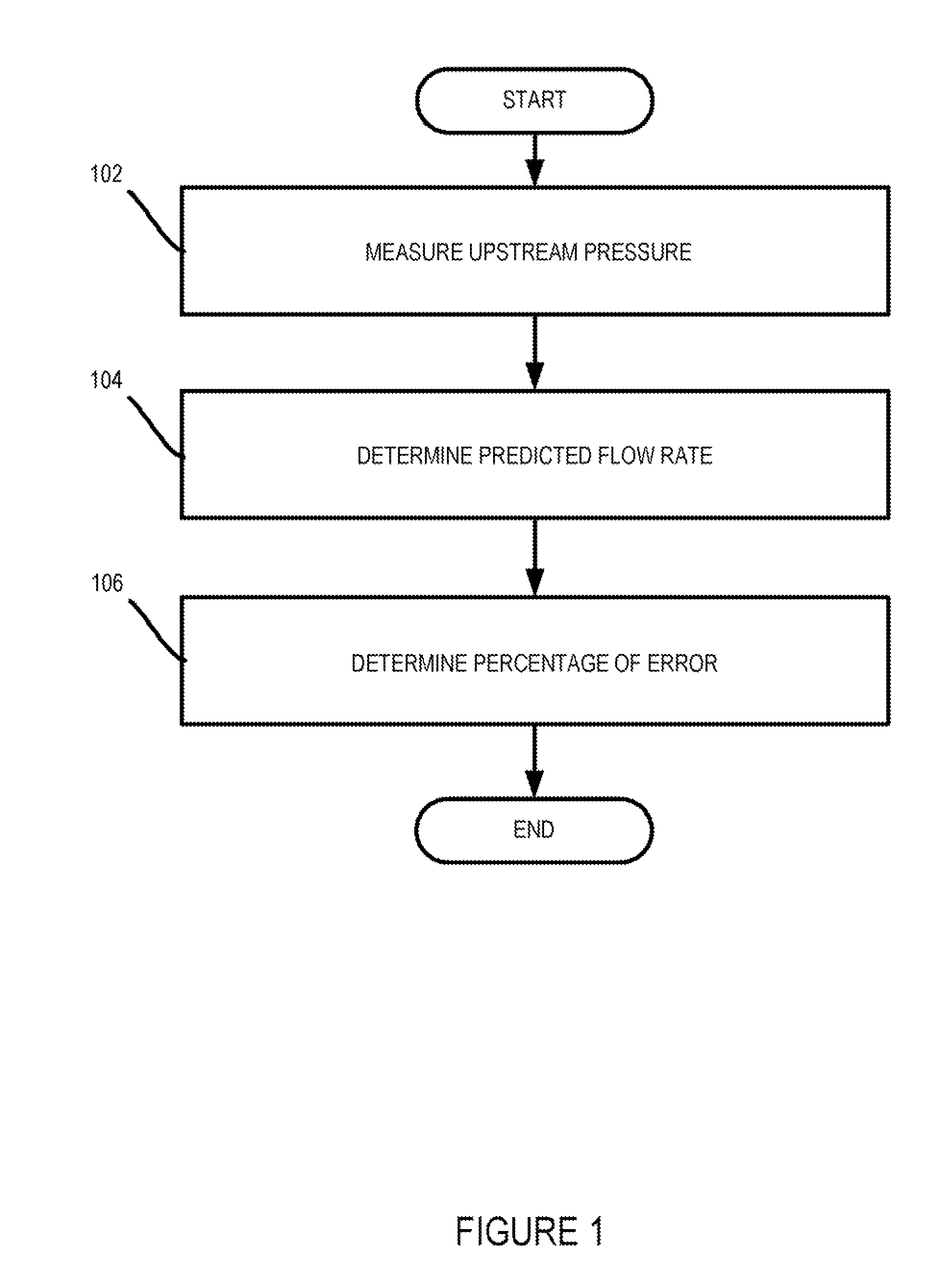
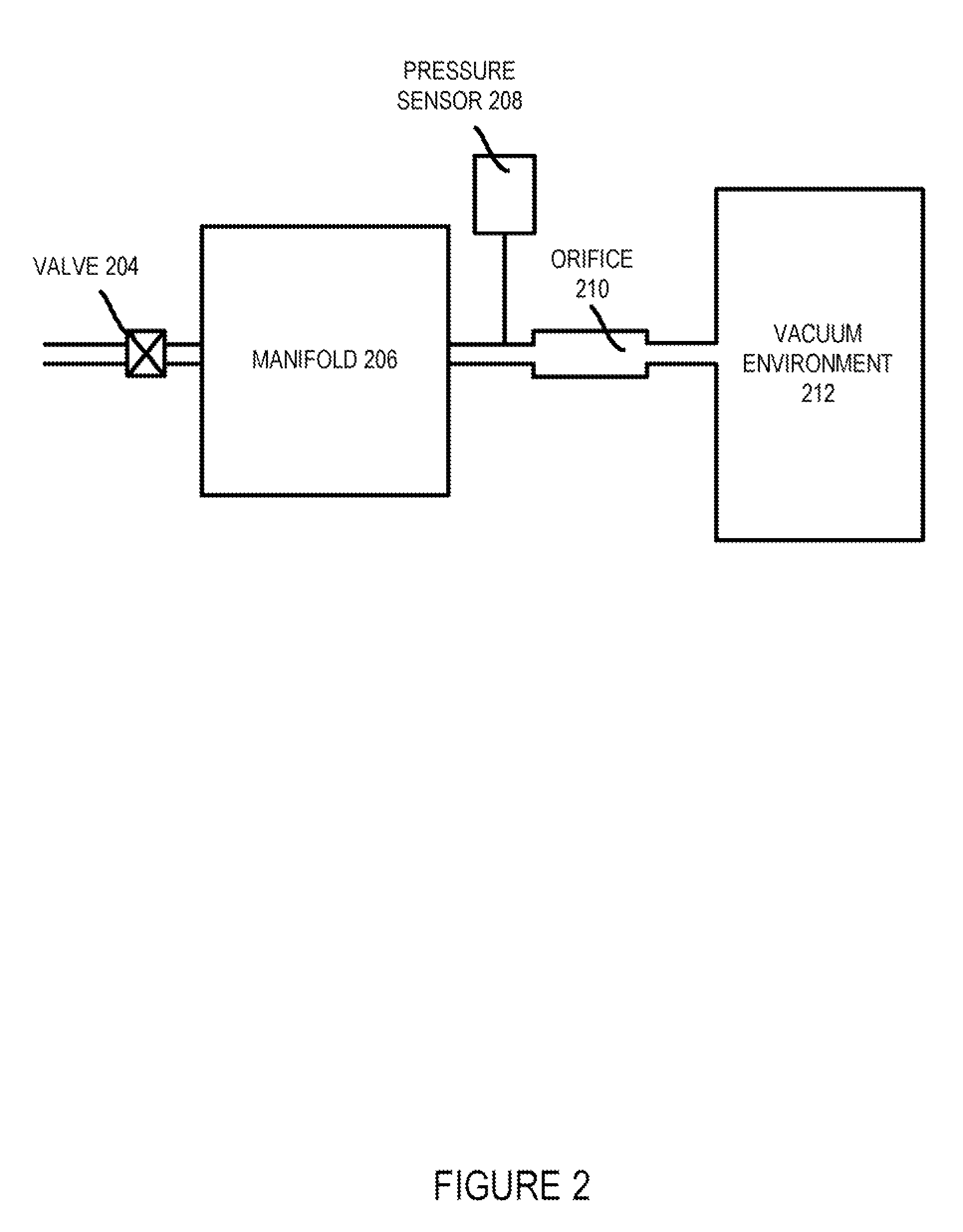
A method for determining an actual gas flow rate as gas flows through a gas flow delivery system is provided. The method includes sending the gas through the gas flow delivery system into a gas conduit, wherein a section of the gas conduit is widened to form an orifice. The method also includes pressurizing the gas to create a choked flow condition within the orifice of the gas conduit. The method further includes measuring upstream pressure of the gas via a set of pressure sensors. The method yet also includes calculating the actual flow rate based on the upstream pressure of the orifice of the gas conduit.

Description

PRIORTY CLAIM[0001]This application is related to and claims priority under 35 U.S.C. §119(e) to a commonly assigned provisional patent application entitled “Methods For Performing Transient Flow Prediction and Verification Using Discharge Coefficient,” by Shareef et al., application Ser. No. 60 / 866,404 filed on Nov. 17, 2006, all of which is incorporated herein by reference.CROSS REFERENCE TO RELATED APPLICATIONS[0002]The present invention is related to the following applications, all of which are incorporated herein by reference:[0003]Commonly assigned application entitled “Methods For Performing Actual Flow Verification,” by Shareef et al., application Ser. No. 60 / 866,406 filed on Nov. 17, 2006, all of which are incorporated herein by reference;[0004]Commonly assigned application entitled “Gas Distribution System with Tuning Gas,” filed on Dec. 31, 2002 by Larson et al., application Ser. No. 10 / 318,612; and[0005]Commonly assigned application entitled “System and Method for Gas Fl...

Claims


Application Information

Patent Timeline
Patent Type & Authority Patents(United States)
IPC IPC(8): G01F25/00
CPCG01F1/36Y10T137/7759Y10T137/0379Y10T137/0368Y10T137/0396Y10T137/7761
Inventor SHAREEF, IQBAL A.TIETZ, JAMES V.WONG, VERNONMEINECKE, RICHARD J.
Owner LAM RES CORP
Learn More