Direct jet impingement-assisted thermosyphon cooling apparatus and method

a cooling apparatus and thermosyphon technology, applied in the direction of electrical apparatus casings/cabinets/drawers, instruments, semiconductor/solid-state device details, etc., can solve the problems of increasing heat load and heat flux, affecting system performance, and device performance challenges, so as to facilitate cooling of respective surfaces and increase cooling

Inactive Publication Date: 2011-02-08
IBM CORP
View PDF67 Cites 33 Cited by
  • Summary
  • Abstract
  • Description
  • Claims
  • Application Information

AI Technical Summary

Benefits of technology

[0006]Briefly summarized, provided herein in one aspect is a cooling apparatus which comprises a cooling subassembly, a pump and a controller. The cooling subassembly includes a jet impingement structure, for directing coolant into a chamber of the subassembly onto a surface to be cooled when in a jet impingement mode, and a thermosyphon associated with the chamber, for facilitating convective cooling of the surface to be cooled via coolant within the chamber when in a thermosyphon mode. The pump actively pumps coolant via the jet impingement structure towards the surface to be cooled when the cooling subassembly is in the jet impingement mode. The controller is coupled to the pump for controlling activation and deactivation of the pump, and also transitioning between the jet impingement mode and the thermosyphon mode. The cooling apparatus provides greater cooling in the jet impingement mode than in the thermosyphon mode, and the controller controls transitioning between the jet impingement mode and the thermosyphon mode depending on cooling requirements for the surface to be cooled.
[0007]In another aspect, a cooling apparatus is provided for cooling a plurality of surfaces to be cooled, each surface to be cooled being, or being coupled to, a surface of a respective electronic device of a plurality of electronic devices to be cooled. The cooling apparatus includes a plurality of cooling subassemblies, a pump and a controller. Each cooling subassembly facilitates cooling of a respective surface to be cooled, and includes a jet impingement structure for directing coolant into a chamber of the cooling subassembly towards the respective surface to be cooled when in a jet impingement mode, and a thermosyphon associated with the chamber for facilitating convective cooling of the respective surface to be cooled via coolant within the chamber when in a thermosyphon mode. The pump actively pumps coolant via the jet impingement structures of the plurality of cooling subassemblies towards the respective surfaces to be cooled of the plurality of surfaces to be cooled when in the jet impingement mode. The controller controls activation and deactivation of the pump, and transitioning of the cooling subassemblies between the jet impingement mode and the thermosyphon mode, wherein greater cooling is provided in the jet impingement mode than in the thermosyphon mode.
[0008]In a further aspect, a method of cooling a surface to be cooled is provided. The surface to be cooled comprises, or is coupled to, a surface of an electronic device. The method includes: obtaining a cooling subassembly for the surface to be cooled, the cooling subassembly including a jet impingement structure for directing coolant into a chamber of the cooling subassembly onto the surface to be cooled when in a jet impingement mode, and a thermosyphon associated with a chamber of the cooling subassembly for facilitating passive convective cooling of the surface to be cooled via coolant within the chamber when in a thermosyphon mode; utilizing a pump to actively pump coolant via the jet impingement structure towards the surface to be cooled when in the jet impingement mode only; and monitoring a temperature of the electronic device and controlling transitioning of the cooling subassembly between the jet impingement mode and the thermosyphon mode, depending on the temperature of the electronic device.

Problems solved by technology

Despite these advantages, providing many electronic devices in a small footprint can create device performance challenges.
One of these challenges is thermal management of the overall environment.
Heat dissipation issues, if unresolved, can result in electronic and mechanical failures that will affect system performance, irrespective of the size of the environment.
In many computing environments, microprocessors continue to increase in performance, with the active circuitry of the microprocessor chip being driven to an ever smaller footprint, leading to ever higher heat loads and high heat fluxes.
Notwithstanding this, reliability constraints often dictate that operating temperature of the devices not exceed a known maximum value.
The existing art has struggled with designing high-performance cooling solutions that can efficiently remove this heat.
Unfortunately, providing greater airflow is not always possible.
Cold plate cooled modules, however, are limited by the presence of intermediate materials and interfaces, which restrict heat transfer capabilities of the module.

Method used


Image

  • Direct jet impingement-assisted thermosyphon cooling apparatus and method
  • Direct jet impingement-assisted thermosyphon cooling apparatus and method
  • Direct jet impingement-assisted thermosyphon cooling apparatus and method

Examples


Embodiment Construction

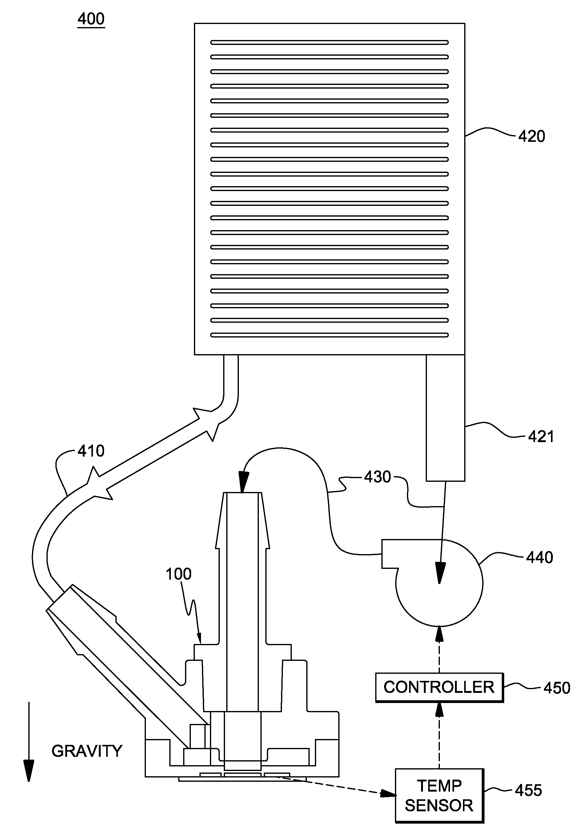
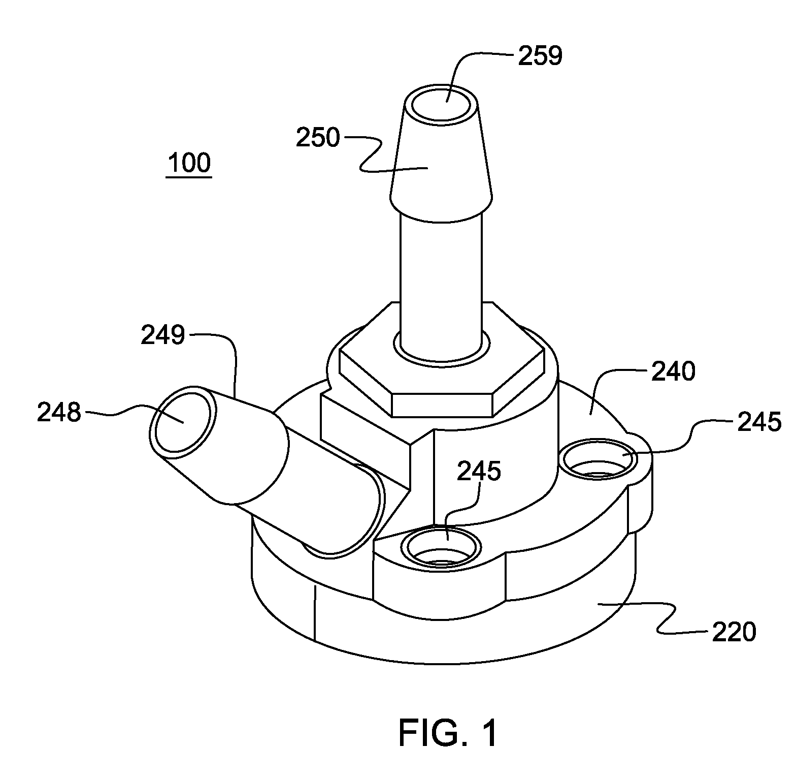
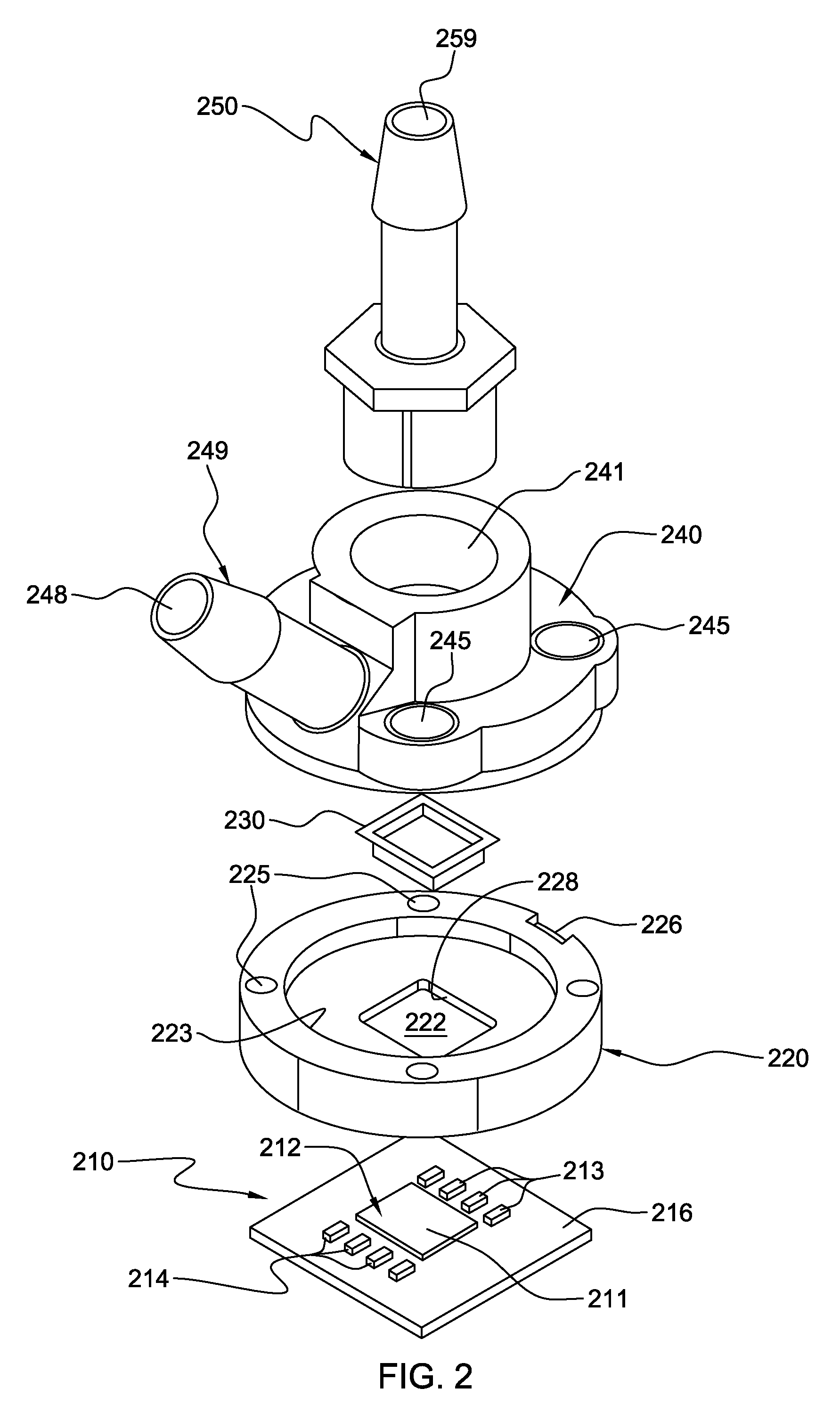
[0023]As used herein, “electronic device” comprises any heat-generating electronic device of a computer system or other electronic system requiring cooling. In one example, the electronic device is or includes an integrated circuit chip, a semiconductor chip and / or any other electronic device requiring cooling. The term “cooled electronic module” includes any electronic module with direct or indirect cooling of an electronic device, with cooled single-chip modules and cooled multi-chip modules being examples of cooled electronic modules, as described herein. In one embodiment, the cooled electronic module disclosed herein employs (in one mode) direct coolant impingement on the surface to be cooled, and is referred to herein as a “direct impingement cooling module”. The “surface to be cooled” refers to a surface of the electronic device itself, or to an exposed surface of a thermal cap, thermal spreader, passivation layer, or other structure in contact with the electronic device, and...


PUM


Abstract

Cooling apparatuses and methods are provided for facilitating cooling of an electronic device utilizing a cooling subassembly, a pump and a controller. The cooling subassembly includes a jet impingement structure, and a thermosyphon. The jet impingement structure directs coolant into a chamber of the subassembly onto a surface to be cooled when in a jet impingement mode, and the thermosyphon, which is associated with the chamber, facilitates convective cooling of the surface to be cooled via boiling of coolant within the chamber when in a thermosyphon mode. The controller, which is coupled to the pump to control activation and deactivation of the pump, also controls transitioning between the jet impingement mode and the thermosyphon mode based on a sensed temperature of the electronic device.

Description

BACKGROUND[0001]The present invention relates in general to heat transfer mechanisms, and more particularly, to cooling apparatuses and methods for removing heat generated by one or more electronic devices. Still more particularly, the present invention relates to fluidic cooling apparatuses and methods for cooling one or more electronic devices.[0002]The industry trend has been to continuously increase the number of electronic devices within computing system environments. Compactness allows for selective fabrication of smaller and lighter devices that are more attractive to the consumer. Compactness also allows circuits to operate at higher frequencies and at higher speeds due to the shorter electrical connection distances in these devices. Despite these advantages, providing many electronic devices in a small footprint can create device performance challenges. One of these challenges is thermal management of the overall environment. Heat dissipation issues, if unresolved, can resu...

Claims


Application Information

Patent Timeline
Patent Type & Authority Patents(United States)
IPC IPC(8): H05K7/20G06F1/20
CPCH01L23/427H01L23/4735H01L2924/0002Y10S165/908H01L2924/00
Inventor CAMPBELL, LEVI A.CHU, RICHARD C.ELLSWORTH, JR., MICHAEL J.IYENGAR, MADHUSUDAN K.SIMONS, ROBERT E.
Owner IBM CORP
Why Eureka
Try Eureka