[0018]Unlike the concept presented in U.S. Pat. No. 7,068,806, this invention decouples the correlation between the
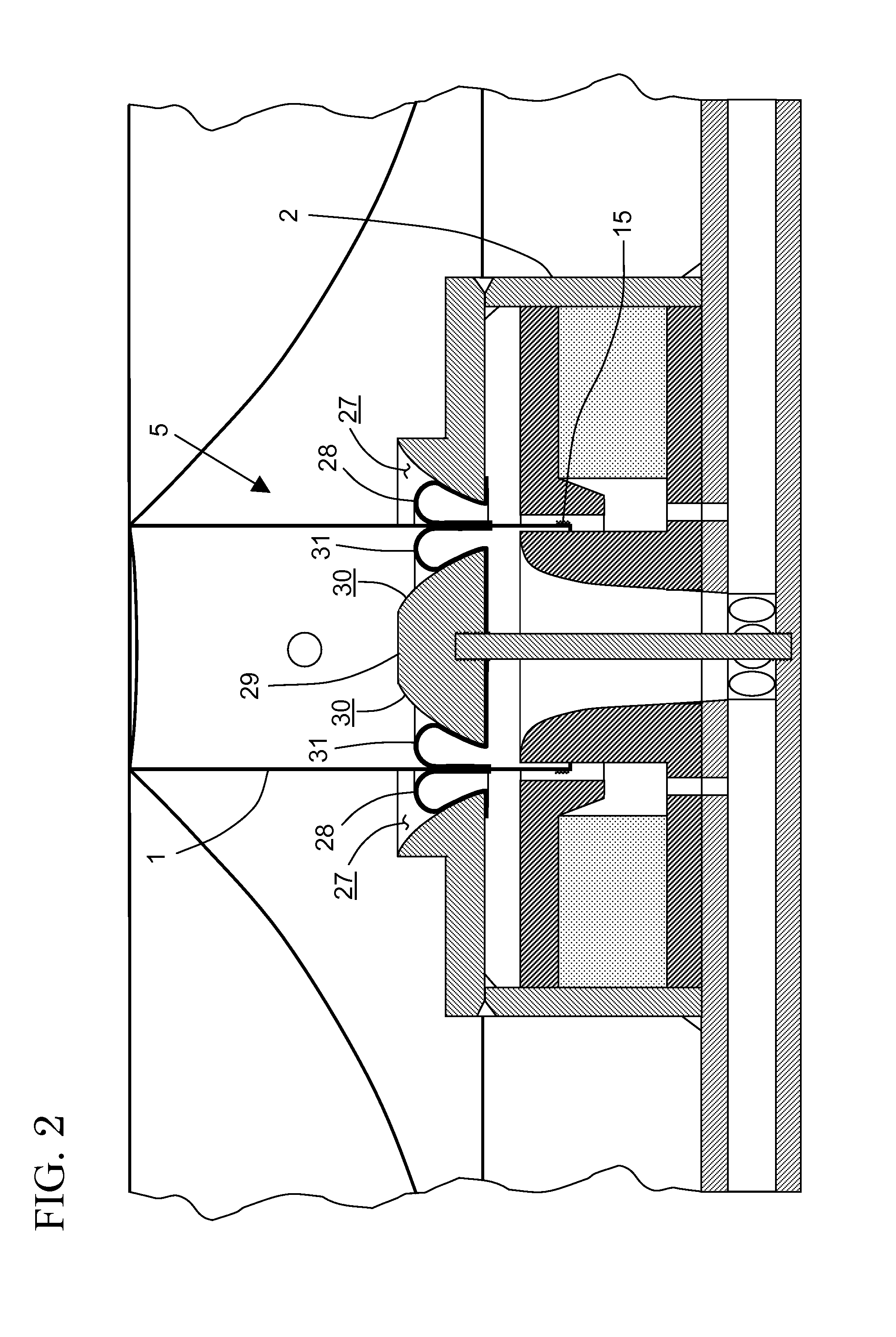
high pressure chamber (or vessel) volume and the resonant frequency of the acoustic radiating diaphragm. This is achieved by the reduction of the working surface area of the tandem seal as the former moves in and an increase of this working surface area as it moves out. Inward movement of the former compresses the enclosed gas or vapor, increasing its pressure. The resulting counter-force is a function of the balance
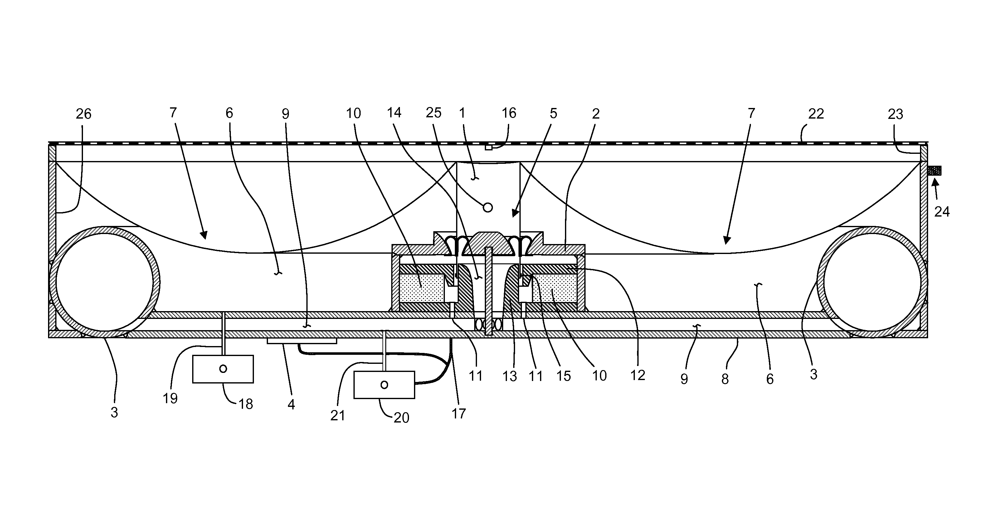
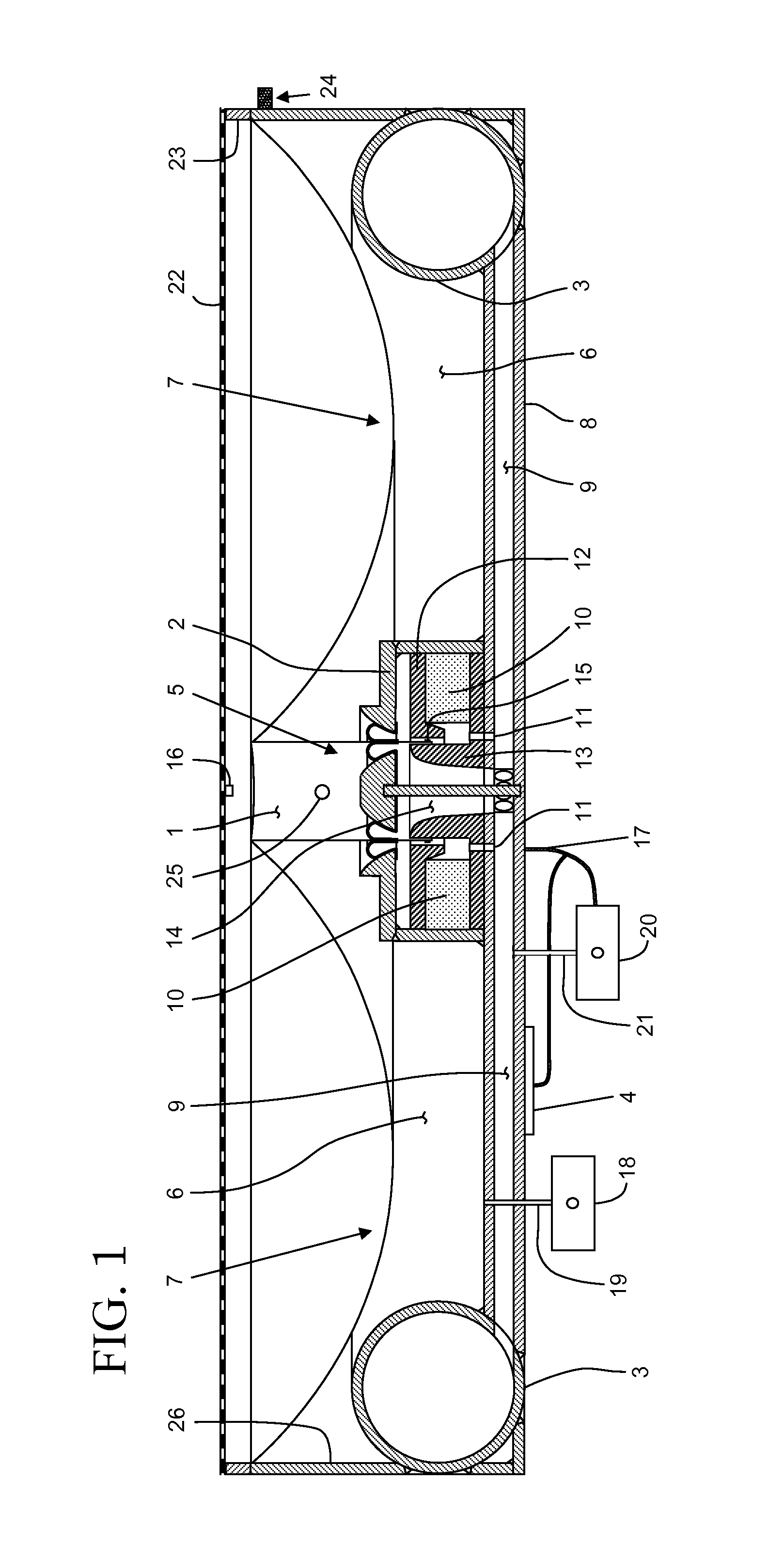
chamber pressure and also the working surface area of the tandem seal. As pressure is increased because of the inward movement, the surface area upon which the gas or vapor acts to counter continued inward movement diminishes, thus reducing the rate (to zero if desired) at which the force increases against it. Conversely, an outward movement of the former decompresses the enclosed gas or vapor, reducing its pressure. As pressure drops because of the outward movement, the surface area on which the gas or vapor acts to facilitate continued outward movement increases, reducing (to zero if desired) the rate at which the facilitating force diminishes. As previously described, the upper inside surface of the pressure cylinder serves as a fixed
support surface for the outer part of the tandem seal
assembly with an axially mounted spool piece, centered within the cylinder, acting as the fixed
support surface of the inner part of the tandem seal. Rather than being parallel to each other in the direction of former travel, the inner and outer fixed support surfaces are curved or tapered to provide the desired force-vs.-position function to achieve a target resonant frequency and / or desired acoustic diaphragm operating behavior. As the meniscuses of the inner and outer parts of the tandem seal move along these fixed support surfaces their radii of curvatures vary as a function of former offset. With an outward movement of the meniscuses, their radii of curvatures increase as the fixed support surfaces diverge from each other in the direction of travel, thus increasing their working surface areas as pressure falls. Conversely, with an inward movement of the meniscuses, their radii of curvatures diminish as the fixed support surfaces converge towards each other in the direction of travel, thus decreasing their working surface areas as pressure increases. The subject invention can theoretically achieve a resonant frequency of <1
Hertz of a large area and lightweight acoustic diaphragm coupled with a shallow
enclosure without resorting to extremely high gas or vapor pressures. Such a low resonant frequency, being infrasonic, ensures phase coherency in the audible frequency range, i.e., approximately 20
Hertz and above.
[0033]The sixth object of the invention is the
elimination of over damping of large area, lightweight acoustic diaphragm excursions operating at very low frequencies by the action of the acoustic diaphragm on a small volume of compressed vapor or gas.

