Loop filtering method, loop filter and phase-locked loop
A loop filter and loop filter technology, applied in the direction of electrical components, automatic power control, etc., can solve problems such as increased power consumption overhead and phase-locked loop circuit complexity.
- Summary
- Abstract
- Description
- Claims
- Application Information
AI Technical Summary
Problems solved by technology
Method used
Image
Examples
Embodiment 1
[0043] According to the embodiments of the present invention, a method embodiment that can be used to implement the device embodiments of the present application can be provided. It should be noted that the steps shown in the flowchart in the accompanying drawings can be implemented in a group of computer-executable instructions. It is executed in a computer system, and although a logical sequence is shown in the flowchart, in some cases, the steps shown or described may be executed in a different order than here.
[0044] According to an embodiment of the present invention, a filtering method is provided. The following specifically introduces the phase-locked loop control method provided by the embodiment of the present invention:
[0045] Figure 4 Is a flowchart of a filtering method according to an embodiment of the present invention, such as Figure 4 As shown, the filtering method mainly includes the following steps S401 to S405:
[0046] S401: Provide an energy storage group, ...
Embodiment 2
[0058] The embodiment of the present invention also provides a loop filter, which is mainly used to implement any of the loop filtering methods provided in the above-mentioned content of the embodiment of the present invention. The following describes the loop filter provided in the embodiment of the present invention. The filter is specifically introduced:
[0059] Figure 5 Is a schematic diagram of a loop filter according to an embodiment of the present invention, such as Figure 5 As shown, the loop filter provided by the embodiment of the present invention mainly includes an energy storage group, a first switch array, a second switch array, and a second energy storage device, where:
[0060] The energy storage group includes m first energy storage devices, Figure 5 The four first energy storage devices are schematically shown in C11, C12, C13, and C14 in sequence. The first end of each first energy storage device is used to receive charge, and the second end is used for ground...
Embodiment 3
[0095] According to the embodiment of the present invention, a phase-locked loop is also provided. The following specifically introduces the phase-locked loop provided by the embodiment of the present invention:
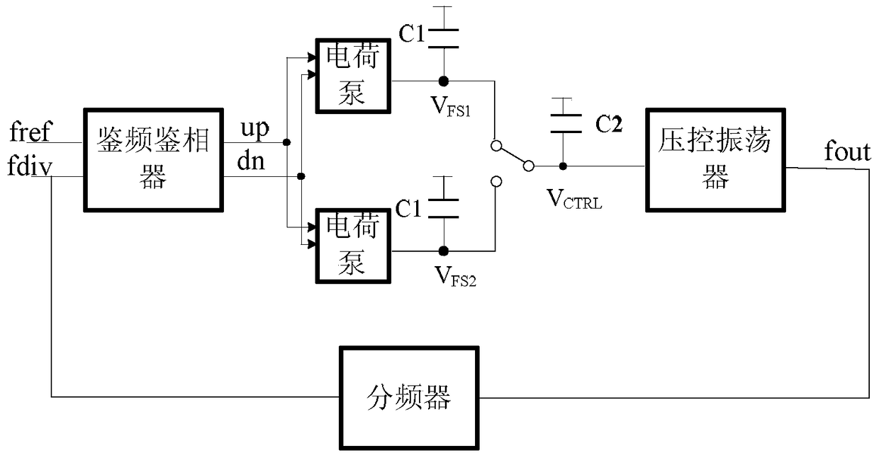
[0096] Figure 7 Is a structural diagram of a phase-locked loop according to an embodiment of the present invention, such as Figure 7 As shown, the phase-locked loop of this embodiment mainly includes: Voltage Controlled Oscillator (VCO), Charge Pumping (CP) and Loop Filter (LPF), in which:
[0097] The charge pump is used to sequentially provide charge to the m first energy storage devices in the loop filter, that is, to cyclically generate a voltage signal on the loop filter, where the charge pump filters in the loop in each cycle. M voltage signals are sequentially generated on the device, m≥4, and m is an integer.
[0098] Specifically, the charge pump mainly outputs electric charge to the energy storage device of the loop filter. The energy storage device accumulates ...
PUM
 Abstract
Description
Claims
Application Information
 - R&D
- Intellectual Property
- Life Sciences
- Materials
- Tech Scout
- Unparalleled Data Quality
- Higher Quality Content
- 60% Fewer Hallucinations
Browse by: Latest US Patents, China's latest patents, Technical Efficacy Thesaurus, Application Domain, Technology Topic, Popular Technical Reports.
© 2025 PatSnap. All rights reserved.Legal|Privacy policy|Modern Slavery Act Transparency Statement|Sitemap|About US| Contact US: help@patsnap.com


