
Loop filtering method, loop filter and phase-locked loop

A loop filter, loop filtering technology, applied in the direction of electrical components, automatic power control, etc., can solve the problems of phase-locked loop circuit complexity, power consumption increase, etc.

Active Publication Date: 2015-11-25
LOONGSON TECH CORP
View PDF4 Cites 3 Cited by
  • Summary
  • Abstract
  • Description
  • Claims
  • Application Information

AI Technical Summary

Problems solved by technology

[0010] The main purpose of the present invention is to provide a loop filtering method, a loop filter, and a phase-locked loop to solve the problem of suppressing the stray noise of the phase-locked loop in the prior art and easily causing the circuit complexity and power consumption of the phase-locked loop raised questions

Method used


Image

  • Loop filtering method, loop filter and phase-locked loop
  • Loop filtering method, loop filter and phase-locked loop
  • Loop filtering method, loop filter and phase-locked loop

Examples


Embodiment 1

[0043] According to the embodiment of the present invention, a method embodiment that can be used to implement the embodiment of the device of the present application can be provided. It should be noted that the steps shown in the flow chart of the accompanying drawings can be executed in a program such as a set of computer-executable instructions computer system, and although a logical order is shown in the flowcharts, in some cases the steps shown or described may be performed in an order different from that shown or described herein.

[0044] According to an embodiment of the present invention, a filtering method is provided. The following describes the control method of the phase-locked loop provided by the embodiment of the present invention in detail:

[0045] Figure 4 is a flowchart of a filtering method according to an embodiment of the present invention, such as Figure 4 As shown, the filtering method mainly includes the following steps S401 to S405:

[0046] S401...

Embodiment 2

[0058] The embodiment of the present invention also provides a loop filter, which is mainly used to implement any of the loop filtering methods provided in the above-mentioned content of the embodiment of the present invention. The following describes the loop filter provided by the embodiment of the present invention The filter is introduced in detail:

[0059] Figure 5 is a schematic diagram of a loop filter according to an embodiment of the present invention, such as Figure 5 As shown, the loop filter provided by the embodiment of the present invention mainly includes an energy storage group, a first switch array, a second switch array and a second energy storage device, wherein:

[0060] The energy storage group includes m first energy storage devices, Figure 5 4 schematically shows four first energy storage devices, which are C11, C12, C13, and C14 in sequence. The first end of each first energy storage device is used to receive charge, and the second end is used to ...

Embodiment 3

[0095] According to the embodiment of the present invention, a phase-locked loop is also provided, and the phase-locked loop provided in the embodiment of the present invention is described in detail below:

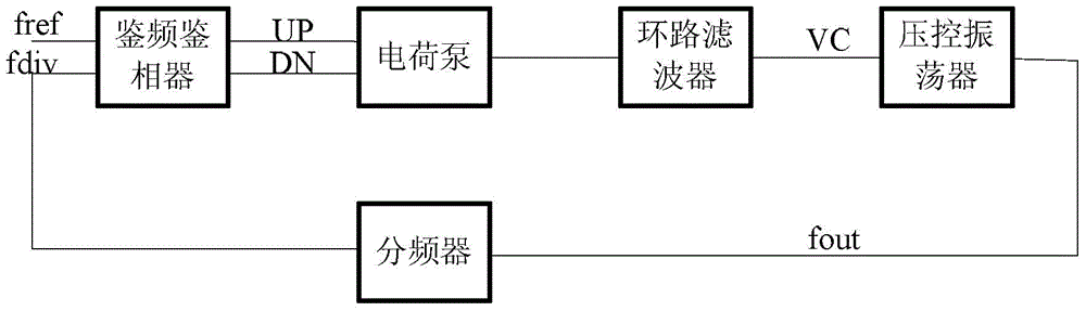
[0096] Figure 7 is a schematic structural diagram of a phase-locked loop according to an embodiment of the present invention, such as Figure 7 As shown, the phase-locked loop of this embodiment mainly includes: a voltage-controlled oscillator (Voltage Controlled Oscillator, referred to as VCO), a charge pump (ChargePumping, referred to as CP) and a loop filter (LoopFilter, referred to as LPF), wherein:

[0097] The charge pump is used to sequentially provide charge to the m first energy storage devices in the loop filter, that is, to generate a voltage signal on the loop filter in a loop, wherein the charge pump performs loop filtering in each cycle m voltage signals are sequentially generated on the device, m≥4, and m is an integer.

[0098] Specifically, the charge ...


PUM


Abstract

The invention discloses a loop filtering method, a loop filter and a phase-locked loop, and solves problems of rising of circuit complexity and power consumption overhead of the phase-locked loop caused by suppressing stray noise of the phase-locked loop in the prior art. The method comprises the steps that an energy storage group is provided, and the energy storage group comprises m first energy storage devices, wherein m is greater than or equal to 4 and m is an integer; charging of the m first energy storage devices is completed in turn in one filtering period, and the filtering period is a time interval of two adjacent times of charging of one first energy storage device; and the first energy storage device of which current charging is completed is controlled to perform charge sharing with other first energy storage devices in the energy storage group apart from the first energy storage device of which current charging is completed during a time period from completion of current charging of the first energy storage device to starting charging again so that filtering voltage is generated.

Description

technical field [0001] The invention relates to the field of circuit design, in particular to a loop filtering method, a loop filter and a phase-locked loop. Background technique [0002] The development of modern science and technology has put forward higher and higher requirements for signal sources, such as wide frequency bandwidth, high frequency resolution, high frequency stability, low phase noise and spurious, and programmable control. Frequency synthesis technology is the main technology to generate a large number of high-precision frequency signals. Phase-locked loop (PhaseLockedLoop, PLL for short) is a circuit that performs frequency synthesis and outputs a relatively stable frequency. The output circuit has been widely used in communication, radar, instrumentation, high-speed computer and navigation equipment. A phase-locked loop is generally composed of a phase-frequency detector, a charge pump, a loop filter, a voltage-controlled oscillator, and a frequency di...

Claims


Application Information

Patent Timeline
IPC IPC(8): H03L7/093H03L7/099
Inventor 杨丽琼王岳
Owner LOONGSON TECH CORP
Learn More