
A High Gain Common Mode Feedback Loop Applied to High Impedance Current Source Load Differential Mode Amplifying Circuit

An amplifier circuit and common-mode feedback technology, which is applied in the field of high-gain common-mode feedback loops, can solve the problems of weakening the effect of common-mode feedback loops, low loop gain self-excited oscillation, etc., and achieve the effect of increasing dynamic range and ensuring gain

Active Publication Date: 2019-01-04
CHENGDU CORPRO TECH CO LTD
View PDF6 Cites 0 Cited by
  • Summary
  • Abstract
  • Description
  • Claims
  • Application Information

AI Technical Summary

Problems solved by technology

At present, the common-mode feedback loops used in various high-impedance differential amplifier circuits with current source loads To ensure the stability of the common-mode feedback loop, the common-mode feedback loop often uses a single-stage amplifier circuit with only a single main pole. The loop gain is often made lower to prevent self-oscillation due to the presence of multiple sub-poles at higher frequencies, which weakens the effect of the common-mode feedback loop

Method used


Image

  • A High Gain Common Mode Feedback Loop Applied to High Impedance Current Source Load Differential Mode Amplifying Circuit
  • A High Gain Common Mode Feedback Loop Applied to High Impedance Current Source Load Differential Mode Amplifying Circuit
  • A High Gain Common Mode Feedback Loop Applied to High Impedance Current Source Load Differential Mode Amplifying Circuit

Examples


Embodiment Construction

[0018] The technical solution of the present invention will be further described in detail below in conjunction with the accompanying drawings, but the protection scope of the present invention is not limited to the following description.

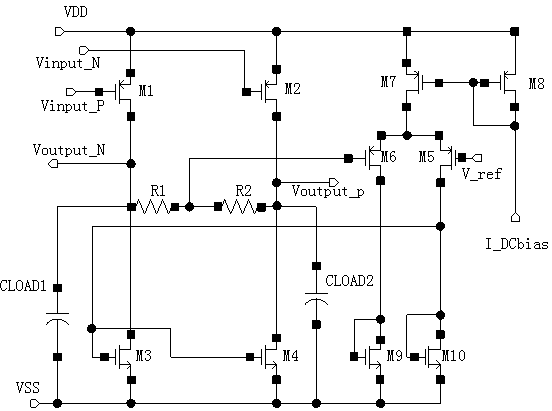
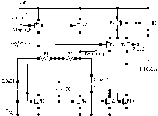
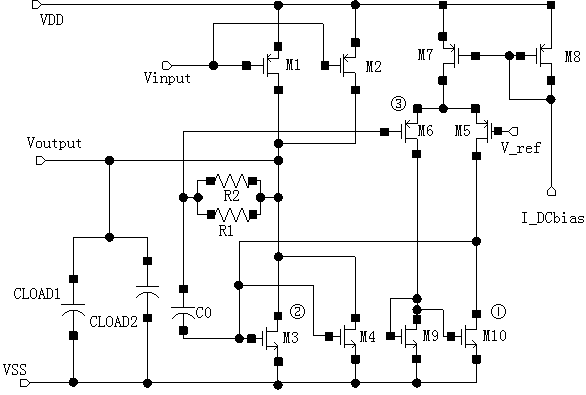
[0019] Such as figure 2 As shown, a high-gain resistance average common-mode feedback loop applied to a high-impedance current source load differential-mode amplifier circuit, which includes two-stage high-gain amplifier circuits and a first-stage RC filter circuit, which includes common-mode signal sampling circuits, The reference voltage source, the first-stage differential comparison amplifier circuit and the second-stage amplifier drive circuit, the two input ends of the common-mode signal sampling circuit are connected to the output of the high-impedance current source load differential-mode amplifier circuit, and the average output of the sampling circuit It is connected with the input end of the first-stage differential comparison a...


PUM


Abstract

The invention discloses a high gain common mode feedback loop applied to a high impedance current source load differential mode amplification circuit. The feedback loop comprises a common mode signal sampling circuit, a reference voltage source, a first level differential comparison amplification circuit and a second level amplification drive circuit; two input ends of the common mode signal sampling circuit are respectively connected with two output ends of an impedance current source load differential mode amplification circuit; an averaging output of the sampling circuit is connected with the input end of the first level differential comparison amplification circuit; the reference voltage source is connected with the other input end of the first level differential comparison amplification circuit; the single end output of the first level differential comparison amplification circuit is connected with the input of the second level amplification drive circuit. Gain of the common mode feedback loop is maximized under the condition that current consumption is not increased, the stability is ensured, a common mode DC (direct current) working point is maximized and stably output, the dynamic range of an output differential signal is effectively increased, and common mode spurious noise on a power supply, the ground and a signal line are inhibited.

Description

technical field [0001] The invention relates to a high-gain common-mode feedback loop applied to a high-impedance current source load differential-mode amplifying circuit. Background technique [0002] In various high-impedance differential output amplifier circuits with current source loads, the common-mode feedback loop has become a necessary auxiliary circuit, which is used to lock the output common-mode DC operating point, effectively increase the dynamic range of the output differential signal and suppress the power / Common-mode spurious noise on the ground / signal line, and the effects of these effects mainly depend on the gain of the common-mode feedback loop. The larger the gain, the better the effect. At present, the common-mode feedback loops used in various high-impedance differential amplifier circuits with current source loads To ensure the stability of the common-mode feedback loop, the common-mode feedback loop often uses a single-stage amplifier circuit with o...

Claims


Application Information

Patent Timeline
Patent Type & Authority Patents(China)
IPC IPC(8): H03F3/45
Inventor 周军
Owner CHENGDU CORPRO TECH CO LTD
Learn More