Distributed engine control system

a control system and engine technology, applied in the direction of electric control, turbine/propulsion engine ignition, instruments, etc., can solve the problems of high data rate, complex and the complexity of the central controller and the communication link between the central controller and the engin

Active Publication Date: 2011-02-15
PRECISION ENGINE CONTROLS
View PDF9 Cites 87 Cited by
  • Summary
  • Abstract
  • Description
  • Claims
  • Application Information

AI Technical Summary

Problems solved by technology

Because monitoring and control of each engine requires multiple transducers per engine, both the central controller and the communications link between the central controller and the engines may become complex and require high data rates.

Method used


Image

  • Distributed engine control system
  • Distributed engine control system

Examples


Embodiment Construction

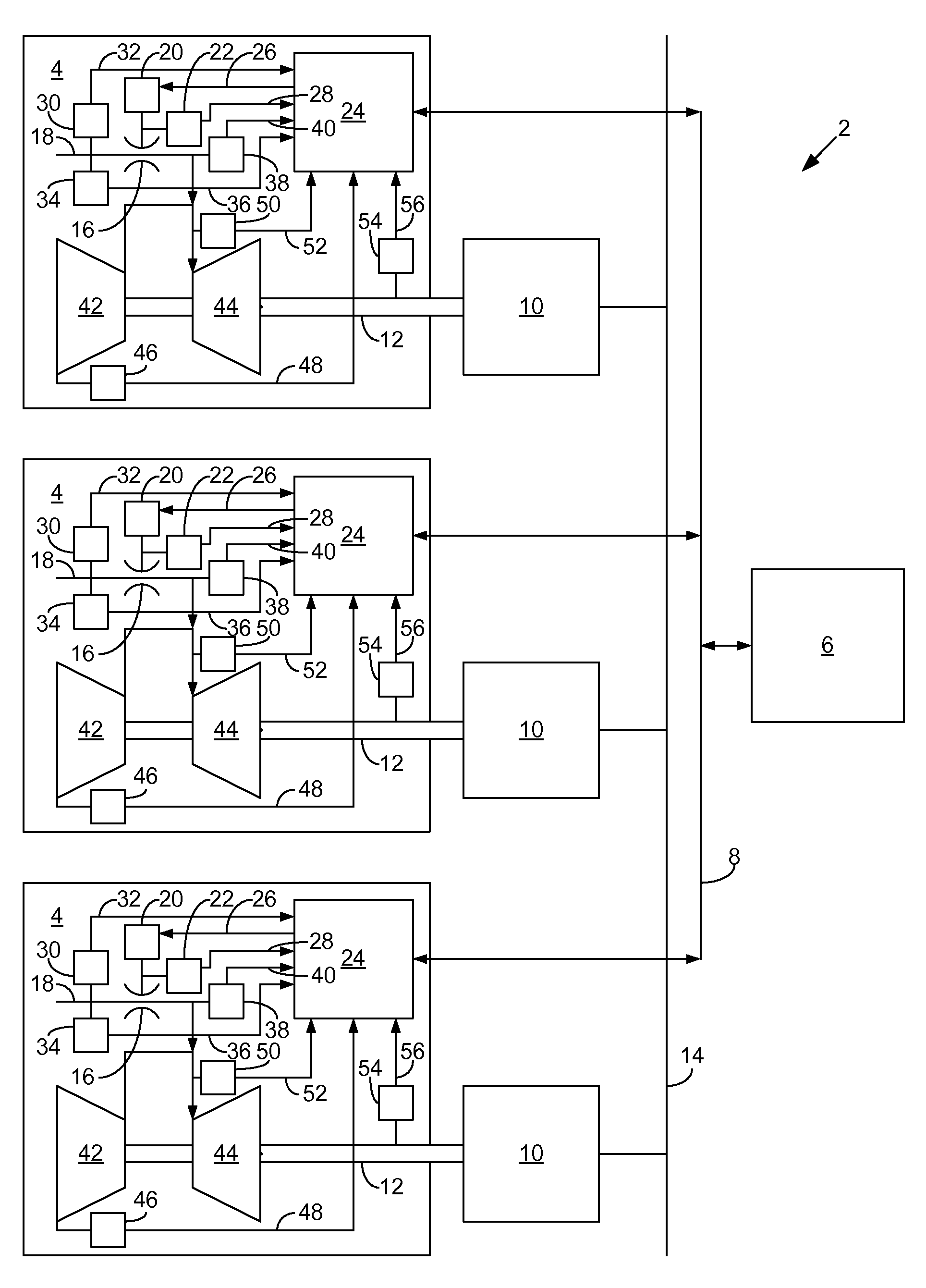
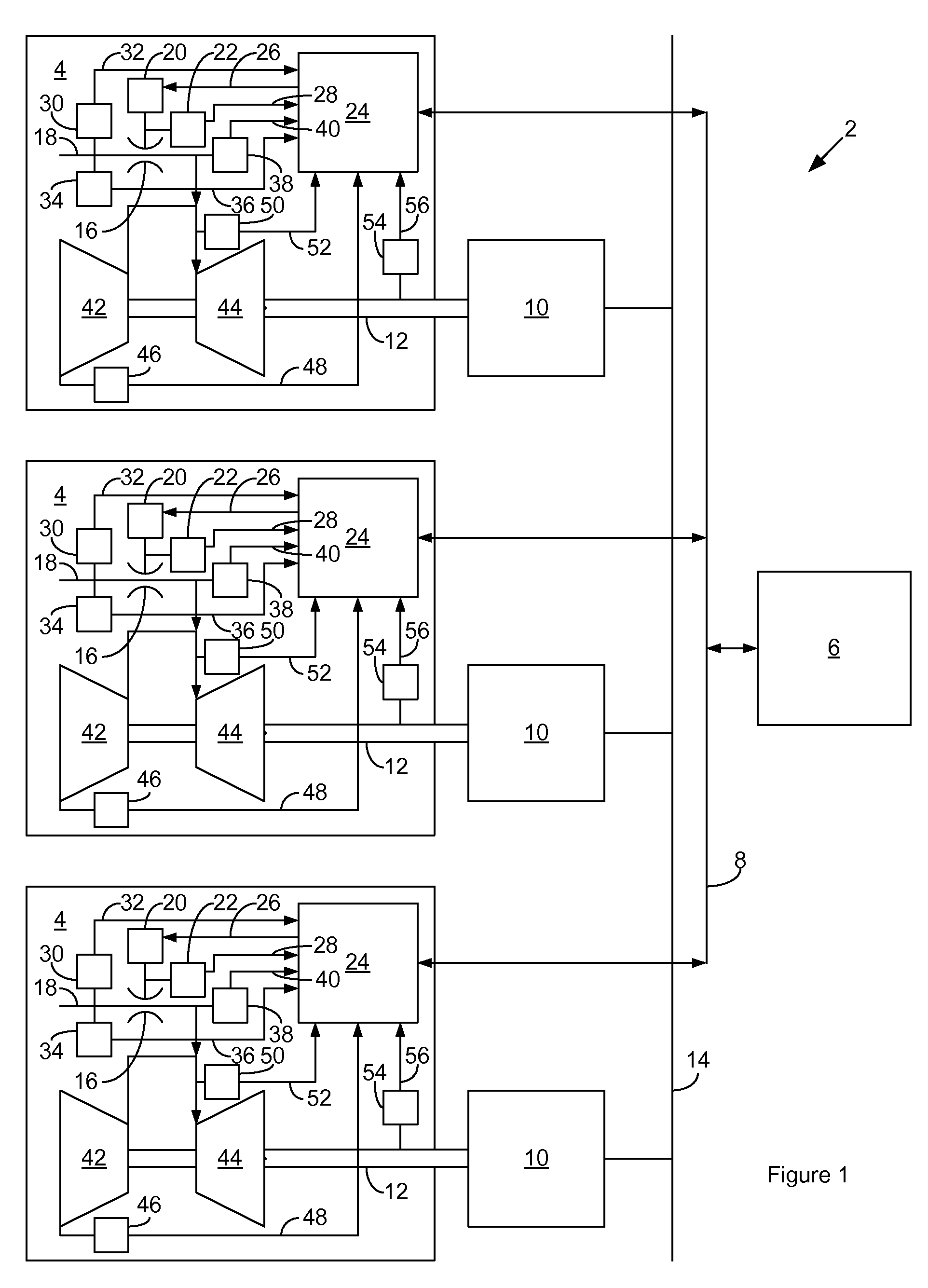
[0006]FIG. 1 is a schematic diagram of distributed engine control system 2 according to a possible embodiment of the invention. The control system comprises multiple engines 4 in communication with a central controller 6 by way of a wired or wireless communications link 8. For purposes of illustration only, FIG. 1 shows three of the engines 4, and engines 4 of the gas turbine type. The control system 2 may alternatively have as little as two engines 4 or more than three engines 4, and the engines 4 may be of another type, such as of the reciprocating internal combustion type. Each engine 4 drives a load 10 by way of an engine drive shaft 12. The load 10 may be mechanical or electrical. By way of example only, FIG. 1 shows each load 10 as an electrical generator, with each electrical generator load 10 coupled to a common electrical grid 14.

[0007]Each engine 14 has a fuel control valve 16 for metering fuel at a fuel metering point along a fuel line 18. The valve 16 has at least a valv...


PUM


Abstract

A method and apparatus for distributing control of multiple engines amongst the engines in a power generation system that has a central controller, comprises the steps of: receiving aboard each engine from the central controller a control signal representative of a desired fuel flow; metering fuel at a fuel metering point aboard each engine; sensing at least one parameter aboard each engine proximate the fuel metering point that is representative of fuel flow; adjusting the fuel metering aboard each engine to cause the sensed parameter to correlate to the desired fuel flow; and transmitting a monitoring signal from each engine to the central controller that is representative of the adjusted fuel metering.

Description

FIELD OF THE INVENTION[0001]The invention relates to engine control systems, and more particularly to control of power systems that comprise multiple engines.BACKGROUND OF THE INVENTION[0002]Many power systems have applications that require multiple engines. For instance, electrical power systems may have multiple gas turbines, each with their own electrical generator load that contributes power to an electrical power grid. It is important to monitor and control the output of the engines so that the power that their respective generators contribute to the grid is such that their total cumulative power stays within a desired cumulative power level range at all times.[0003]Control systems for controlling the power of the engines in the system generally rely on the function of a central controller for monitoring and controlling the operation of all the engines in the system. Because monitoring and control of each engine requires multiple transducers per engine, both the central control...

Claims


Application Information

Patent Timeline
Patent Type & Authority Patents(United States)
IPC IPC(8): F02C1/00F02C9/26F02B63/00
CPCF02C9/263F02C9/42F02D41/40F02D41/021Y02T10/44Y02T10/40Y10S123/08
Inventor JERRELL, JAMES GREGORYZAFUTA, PAUL D.
Owner PRECISION ENGINE CONTROLS
Why Eureka
Try Eureka