Dynamo apparatus for boat

a dynamo apparatus and boat technology, applied in the direction of mechanical energy handling, vessel auxillary drives, transportation and packaging, etc., can solve the problems of reducing cooling efficiency and low airing efficiency, and achieve the effect of efficient cooling, simple and cheap airing structure, and efficient cooling of dynamo apparatus

Inactive Publication Date: 2011-02-15
YANMAR POWER TECHNOLOGY CO LTD
View PDF14 Cites 4 Cited by
  • Summary
  • Abstract
  • Description
  • Claims
  • Application Information

AI Technical Summary

Benefits of technology

[0018]The present invention constructed as above brings the following effects.
[0019]According to claim 1, cooling air flows in the casing by the drive of the fan from the intake hole at the side of the power transmission device to the exhaust hole at the side of the engine, whereby the dynamo apparatus constructed around the power transmission shaft is cooled efficiently by simple and cheap airing structure.
[0020]According to claim 2, in addition to the above-mentioned airing structure along the power transmission shaft, cooling air taken in through the intake hole at an inner peripheral side of a blade of the fan is spread to the exhaust hole at the outer peripheral side thereof, whereby the cooling air is easy to be spread to the whole dynamo apparatus so as to cool the dynamo apparatus more efficiently.
[0021]According to claim 3, the exhaust hole provided at the side of the engine is not formed in not the connection surface at the side of the engine covered by the engine or a flywheel housing but on the outer peripheral surface so as to secure enough opening area of the exhaust hole, whereby cooling air is discharged from the side of the engine efficiently.
[0022]According to claim 4, by increasing the number of the intake holes, cooling efficiency is improved further. By arranging the intake holes on the circle centering on the power transmission shaft, intake effect of each intake hole is equal and each intake hole is constructed compactly.
[0023]According to claim 5, the dynamo apparatus is constructed compactly. An electric leak can be provided easily. The terminal block or the connector is arranged at the position higher than the draft. The wiring can be maintained easily.

Problems solved by technology

Then, with regard to the conventional air cooling structure for the dynamo apparatus, the airing efficiency is low so as to reduce the cooling efficiency.

Method used


Image

  • Dynamo apparatus for boat
  • Dynamo apparatus for boat
  • Dynamo apparatus for boat

Examples


Embodiment Construction

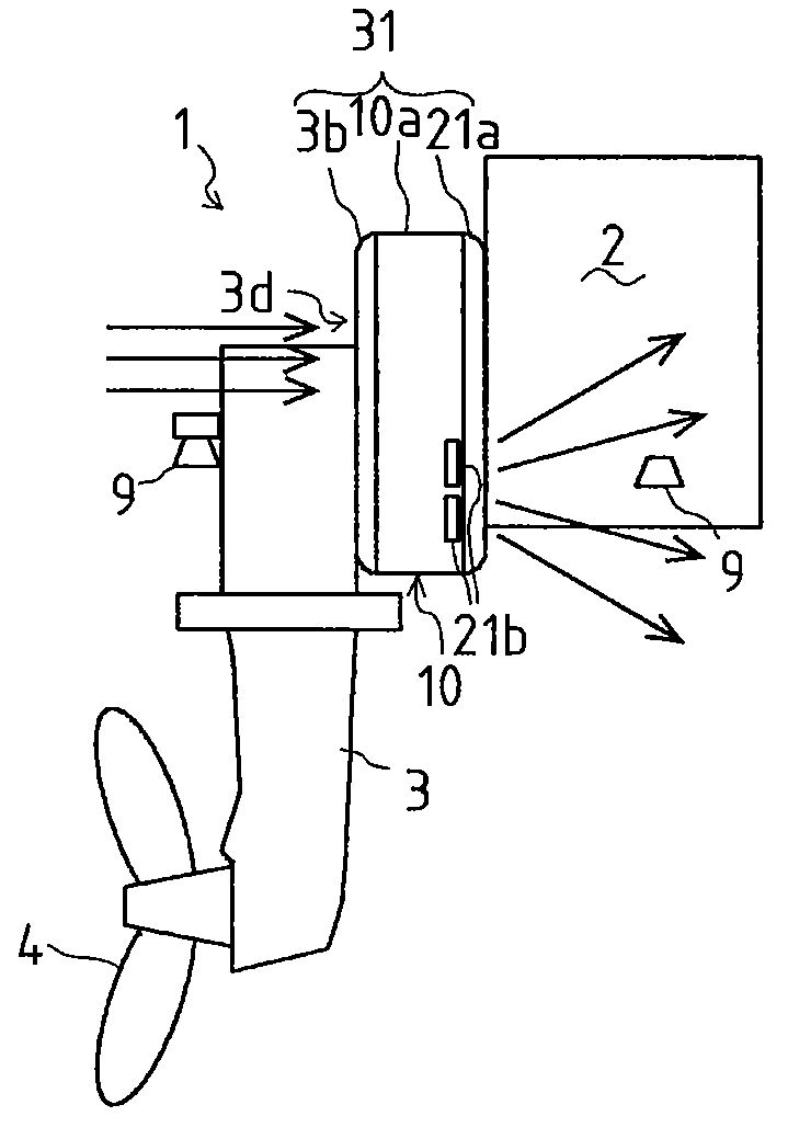
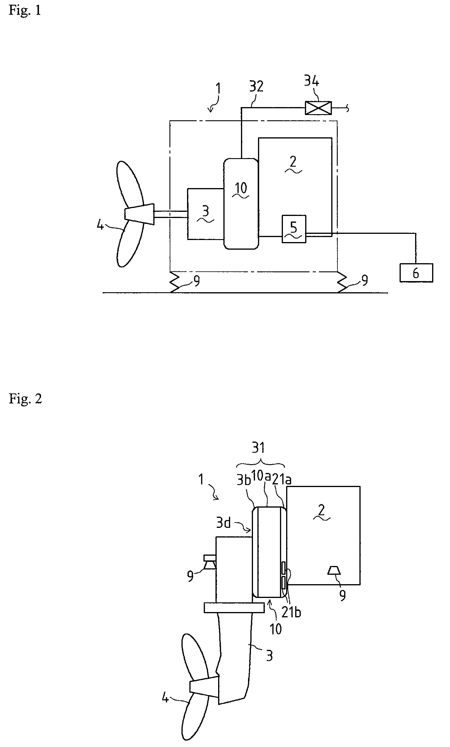
[0034]Next, explanation will be given on the mode for carrying out the present invention. A propelling device 1 for a boat shown in FIG. 1 comprises an engine 2 and a power transmission device 3, and a screw 4 is connected to the power transmission device 3. Driving force of the engine 2 is transmitted to the screw 4 through the power transmission device 3 while decelerated, whereby the screw 4 is driven rotatively.

[0035]An alternator 5 is provided to the engine 2 and driven by the engine 2. Electric power generated by the alternator 5 is stored in a battery 6.

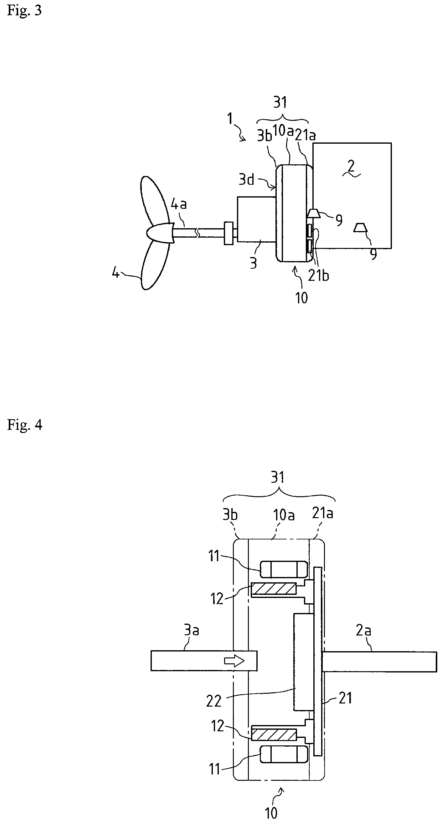
[0036]Furthermore, with regard to the propelling device 1, a dynamo apparatus 10 which is a dynamo or an apparatus having dynamo characteristics is interposed between the engine 2 and the power transmission device 3. The dynamo apparatus 10 is driven by the engine 2, and electric power generated by the dynamo apparatus 10 is supplied to the inboard.

[0037]In addition, the propelling device 1 may be constructed as a sail drive t...


PUM


Abstract

A casing (31) is provided around a power transmission shaft (3a) interposed between a crankshaft (2a) of an engine (2) and a power transmission device (3). A dynamo apparatus (10) and a cooling fan (23) cooling the dynamo apparatus are constructed in the casing (31) around the power transmission shaft (3a) and are driven by the power transmission shaft (3a). The casing (31) is cylindrical and comprises a connection surface at a side of the engine (2), a connection surface at a side of the power transmission device (3) and an outer peripheral surface between the connection surfaces. Intake holes (3d) are formed in the connection surface (3e) of the casing (31) at the side of the power transmission device and the intake hole is formed at an inner peripheral side of a blade of the fan, and are arranged on a circle centering on the axial direction of the connection surface (3e) at an inner peripheral side of blades (23a) of the fan (23). An exhaust hole (21b) is formed in a portion (21a) of the casing (31) at the side of the engine.

Description

BACKGROUND OF THE INVENTION[0001]1. Technical Field[0002]The present invention relates to a dynamo apparatus for a boat, wherein the boat has a sail engine and a dynamo apparatus supplying electric power to the inboard.[0003]2. Background Art[0004]A propelling device of a boat comprises an engine and a power transmission device. Driving force of the engine is reduced in speed by the power transmission device and then drives a screw connected to the power transmission device. A dynamo apparatus is disposed between the engine and the power transmission device. The engine output drives the dynamo apparatus while driving the screw, and the output electric power of the dynamo apparatus is supplied to the inboard. Such an art is disclosed by the Patent Literature 1 or 2.[0005]With regard to construction of the above-mentioned conventional dynamo apparatus, it is cooled by making cooling water pass inside the dynamo apparatus. It is thus necessary to provide a pump taking cooling water in ...

Claims


Application Information

Patent Timeline
Patent Type & Authority Patents(United States)
IPC IPC(8): H02K9/00
CPCB63J3/02H02K5/20H02K5/225H02K7/1815H02K9/06H02K5/207
Inventor MORI, HISANORI
Owner YANMAR POWER TECHNOLOGY CO LTD
Why Eureka
Try Eureka