Perimeter protection systems

a security system and perimeter protection technology, applied in the field of perimeter security systems, can solve problems such as the alteration of the state of the trigger device in the electrical circuit of the circuit, and achieve the effects of reducing the size of the line and corner post, reducing the size of the post foundation, and fast and simple installation

Active Publication Date: 2011-02-15
WINKLER GREGORY ROBERT +1
View PDF14 Cites 24 Cited by
  • Summary
  • Abstract
  • Description
  • Claims
  • Application Information

AI Technical Summary

Benefits of technology

[0018]The utilities utilizing vertical pre-tensioned wires within a modular frame provide a number of advantages over existing systems. These advantages include greater precision intrusion location than traditional horizontal taut wire systems. The vertical wires when constructed from Razor or Barbed wire provide a visual and physical deterrent to intrusion. However, the use of smooth vertical wires terminating in upper and lower rails integrated with support fence posts results in a far more pleasing and less intrusive or threatening system than the horizontal barbed wires and spiral intermediate supports, sensor posts and anchor posts of conventional taut wire systems.
[0034]In one exemplary embodiment such signals are transmitted to the digital signal analyzers either as AC waveforms, resistive changes or dry contact changes. Fixed band-pass filters located on the digital signal analyzer inputs eliminate unwanted noise and inappropriate signals. Each signal analyzer is therefore only responsive to frequencies within the associated filter pass-band frequency settings. The original unfiltered signal input that is generated by a variety of sensor devices is passed through an adjustable amplitude control that may only allow through any increase in signal strength that exceeds a preselected threshold at a preprogrammed rate of rise. This control may also be configured to modify the rate of reduction of allowable amplitude of the input signal at an adjustable rate. This feature provides the system with an adaptive logic control that will change the system sensitivity to better cope with surreptitious forms of attack and to reject environmental interference.

Problems solved by technology

Movement of that wire may result in the trigger device altering the state of an electrical circuit.

Method used


Image

  • Perimeter protection systems
  • Perimeter protection systems
  • Perimeter protection systems

Examples


Embodiment Construction

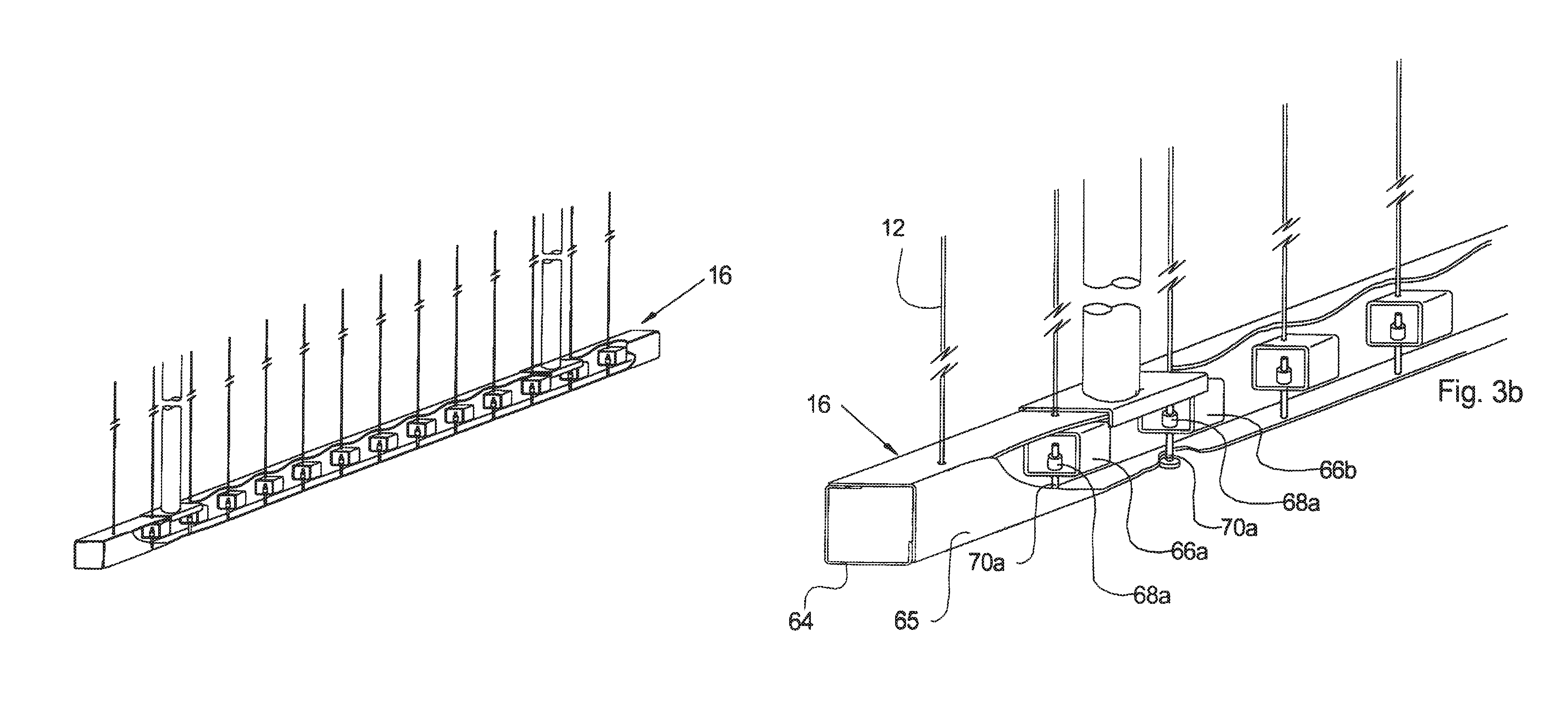
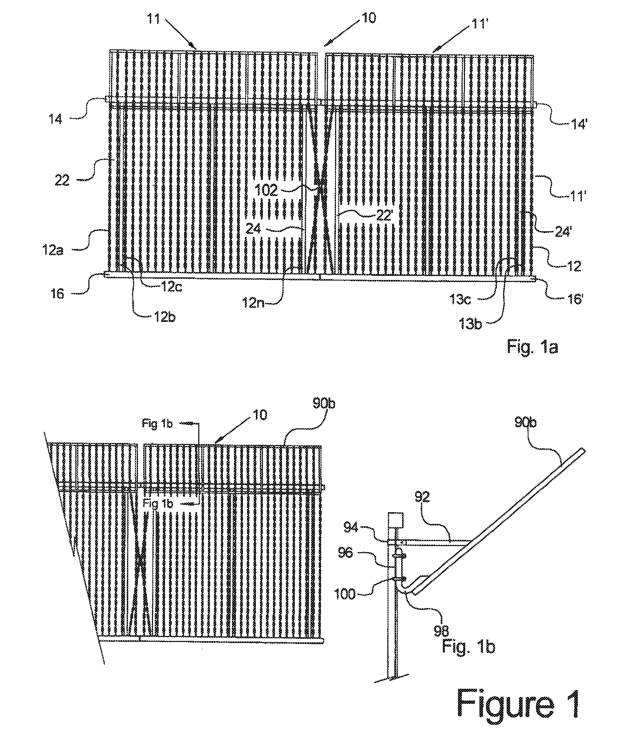
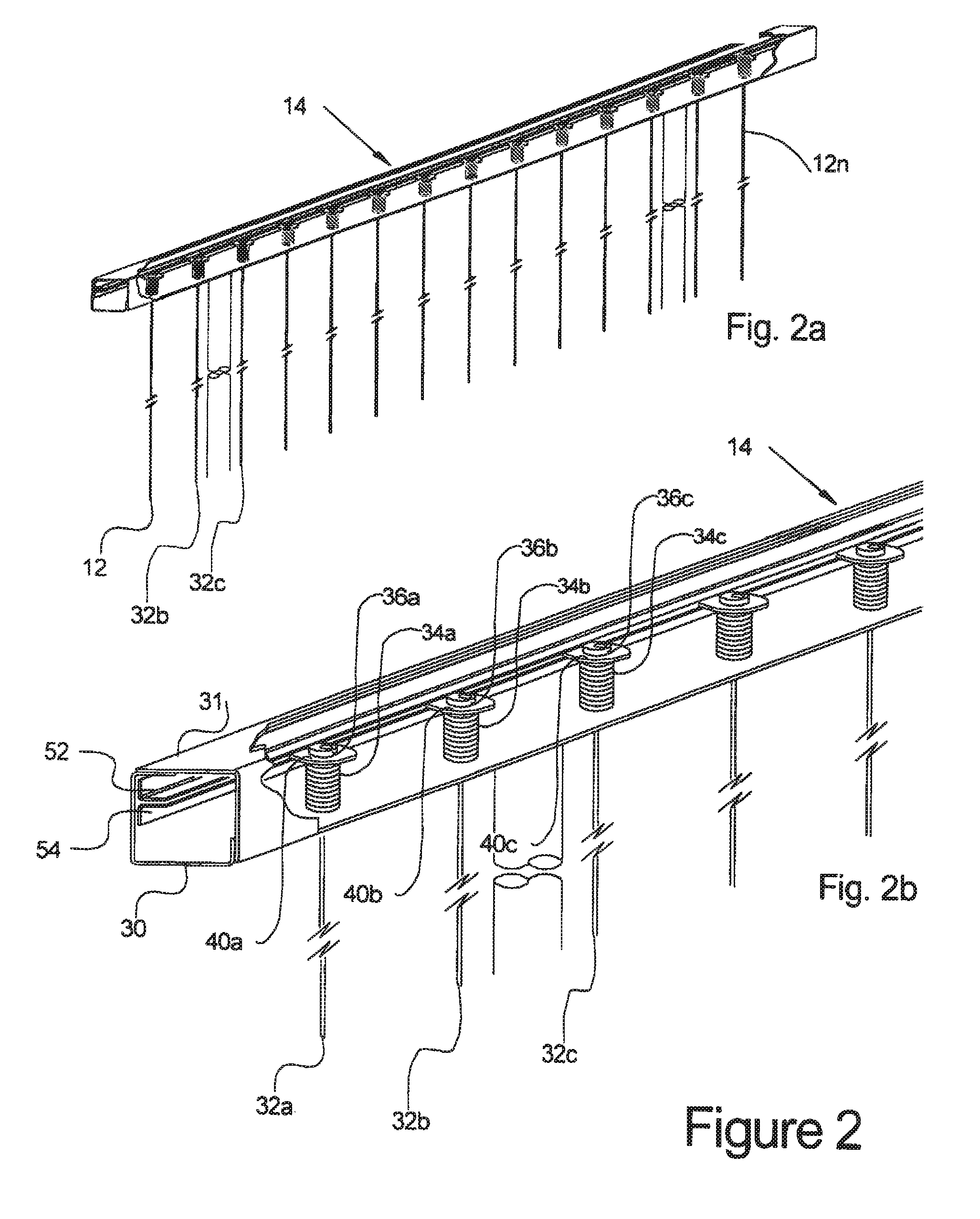
[0054]FIG. 1a illustrates a vertical wire security barrier fence 10 in accordance with one aspect of the invention. In the illustrated embodiment, each panel 11 of the fence 10, includes a plurality of vertical wires 12a-n of each panel 11 tensioned between two horizontal rails 14 and 16, as described in more detail in FIGS. 2a, 2b, 2c and 2d. It will be appreciated that wires 12, etc. shown in FIG. 1a are razor wire, desirable in many cases for maximizing physical deterrence, but when aesthetic considerations are paramount and herein for ease of illustration, the wires indicated in FIG. 2 are shown as smooth wire. Typically a smooth, commercially available, hardened, 14 gauge (0.078 inches diameter) stainless steel wire could be used for this purpose. The vertical taut wires 12 may in one embodiment be spaced from 3 to 4 inches apart along the horizontal rails 14 and 16. The horizontal rails 14 and 16 are rigidly spaced and supported by end posts 22 and 24, as seen in FIG. 1a. The ...


PUM


Abstract

A detection system comprising a plurality of taut wire panels having vertical detection / sensor wires. The sensor wires are tensioned to position trigger plates associated one or more of the wires. Trigger plate movement causes an actuating means to indicate a sensor wire has been moved. In one embodiment, sensor wires and portions of the panel frame have similar coefficients of thermal expansion to substantially eliminate environmental expansion effects that may result in false alarms. Linked sensor wires on adjacent panel may signal movement of entire panels. Panels are monitored by panel controllers reporting to sector controllers that report to a central command computer that automatically numbers sector and panel controllers at start-up. Bi-directional communication enables alarms and system faults to be precisely located.

Description

CROSS REFERENCE[0001]This application claims the benefit of U.S. Provisional Application No. 60 / 862,739, entitled “MOTION DETECTION APPARATUS AND METHOD SECURITY SYSTEM,” having a filing date of Oct. 24, 2006, the entire contents of which are incorporated herein by reference.FIELD[0002]The present inventions are directed toward perimeter security system and methods for detecting physical moment. More specifically in one aspect a modular taut wire fencing system is provided for detecting movement and in another aspect a flexible linear sensor system is provided for detecting movement of a fence or other structure to which the sensor is attached.BACKGROUND[0003]It is recognized that a wide variety of configurations of perimeter security fencing are required in order to service the many terrains to be followed, shapes to be enclosed and fence types utilized. For example, it is well known that existing taut-wire security systems provide a formidable barrier using multiple, closely space...

Claims


Application Information

Patent Timeline
Patent Type & Authority Patents(United States)
IPC IPC(8): G08B13/00G08B13/08E04H17/02G08B13/12
CPCG08B13/122
Inventor WINKLER, GREGORY ROBERTKERR, REGINALD JOHN
Owner WINKLER GREGORY ROBERT
Why Eureka
Try Eureka