
Complementary waveplate rotating compensator ellipsometer

a compensator and waveplate technology, applied in the field of ellipsometry, can solve the problems of inability to tell the handness of the reflected elliptical mode, loss of all data, and increased measurement sensitiveness, and achieve the effect of facilitating operation

Active Publication Date: 2011-02-15
KLA TENCOR TECH CORP
View PDF17 Cites 29 Cited by
  • Summary
  • Abstract
  • Description
  • Claims
  • Application Information

AI Technical Summary

Benefits of technology

[0047]To facilitate operation at the lower end of the wavelength range, e.g., in the deep UV, ellipsometers of the type depicted in FIG. 4 and FIG. 6 may be configured to permit the beam path to be purged with an inert gas, such as nitrogen. Specifically, the optical components of the ellipsometer may be loca

Problems solved by technology

Ellipsometric measurements can be done in transmission or reflection, however, for applications that are specifically targeted at surface processes reflection measurements are more sensitive.
This is a particular disadvantage for measuring very thin films, or whenever the thickness of an overlayer meets a resonance condition, i.e. for which the phase shift between p- and s-waves is an integer multiple of π. In these situations, all data is lost.
In addition, the cosine is a symmetric function around Δ=0 and hence rectifies the phase shift, so that it is not possible to tell the handedness of the reflected elliptical mode.
Broadband operation is essential for many applications, however, rotating compensator systems are not ideally suited for it.
The difficulty encountered with RCE operation is a consequence of the fact that the retardation of the waveplate depends on the wavelength of light approximately as 1 / λ,λ being the wavelength, yet the retardation needs to be that of a quarter wave over the entire spectral range for best sensitivity.
Reducing the wavelength further, the sensitivity initially increases, assumes a second maximum at 270° but then hits a dead zone around 360° retardation, for which an RCE returns no phase information at all but becomes a simple off-axis reflectometer, which is even less useful than an RPE.
However, these devices are non-trivial and expensive to manufacture, they are significantly bigger and heavier than a standard waveplate, and they feature unevenly distributed moments about the optical axis.
Hence achromatic retarders are more difficult to use in a continuously, fast-rotating configuration than standard waveplates.
In summary, current single rotating compensator designs employ a waveplate that works reasonably well over a wide spectral range, yet, due to the dispersive nature of the material out of which the waveplate is constructed (typically MgF2), the sensitivity is compromised at either the extremely short-or long wavelengths, or at both extremes.

Method used


Image

  • Complementary waveplate rotating compensator ellipsometer
  • Complementary waveplate rotating compensator ellipsometer
  • Complementary waveplate rotating compensator ellipsometer

Examples


first embodiment

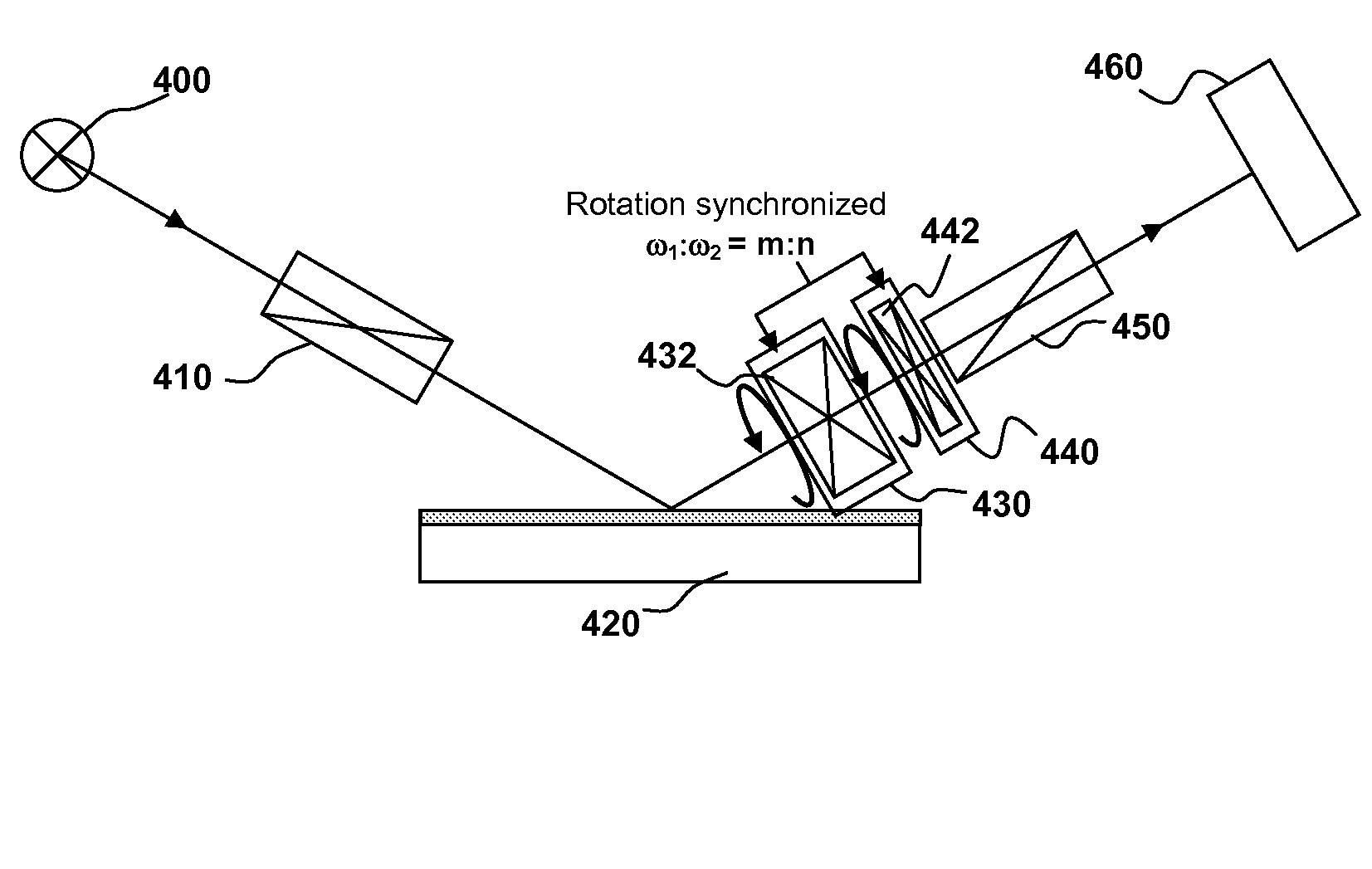
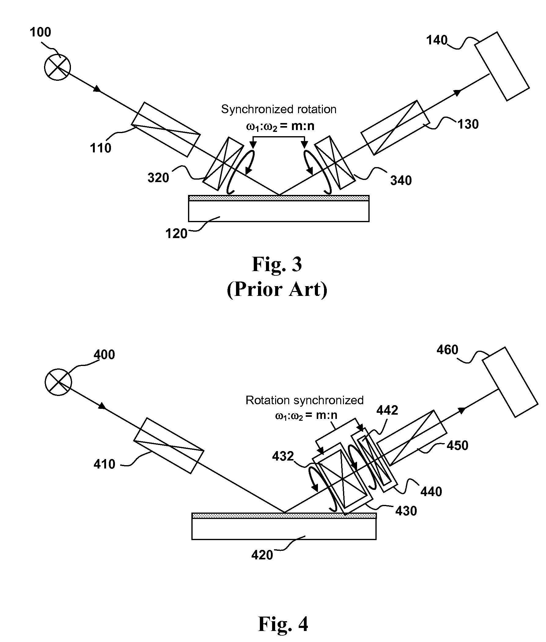
[0031]In contrast, FIG. 4 shows the novel complementary dual rotating compensator ellipsometer disclosed herein. It enables the user to select specifically two waveplates 430 and 440 of different thickness so that their respective quarter wave retardation occurs at different wavelengths. The sole purpose of this configuration is to increase the wavelength range of useful sensitivity and to optimize the sensitivity over all available wavelengths.

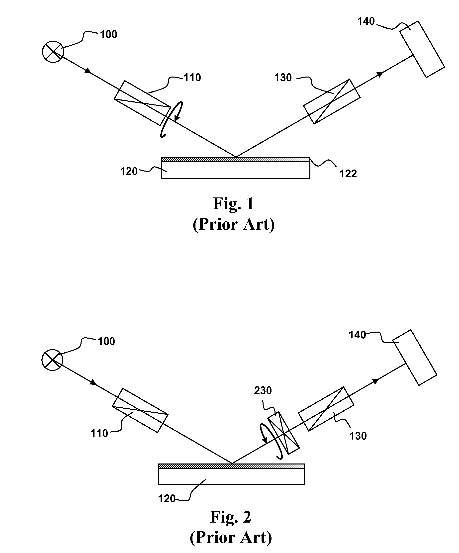
[0032]In the embodiment illustrated in FIG. 4, referred to herein as the single waveplate equivalent configuration, both waveplates are located next to each other on the same side of the sample. In the (idealized) case of truly complementary waveplates, this configuration returns the same information as a single rotating compensator system, since the incident light has the same polarization state as in the RCE configuration of FIG. 2, yet the useful wavelength range for the system is much extended. Specifically, the second waveplate does not ...

second embodiment

[0042]In the complementary waveplate dual rotating compensator ellipsometer two compensator assemblies having waveplates of different thickness are located on either side of a sample 630 as illustrated in FIG. 6. In this embodiment two compensators having waveplates of specific and different thickness are mounted on either side of the sample 630 in a so-called symmetric configuration In particular the ellipsometer has a source 600—Polarizer 610—First compensator assembly 620—Sample 630—Second Compensator assembly 640—Analyzer 650—Detector 660 configuration. However, depending on the application, it may be somewhat less ideally suited for the sole purpose of extending the available wavelength range since the incident polarization is being affected by the rotating waveplate, which could make the reflected beam of light more sensitive to additional sample properties, such as the reflection differences of the sample depending on the azimuth of the sample relative to the direction of pol...


PUM


Abstract

Ellipsometry using two waveplates of complementary retardation in a dual rotating compensator configuration is disclosed. Two waveplates of complementary retardation may be used to increase the useful spectral range of a rotating compensator ellipsometer, in particular towards the deep Ultraviolet (UV) spectrum. The improved rotating compensating ellipsometer disclosed herein enables a user to select specific and different waveplate retardations for the purpose of increasing the operating wavelength range of the rotating compensating ellipsometer.

Description

CLAIM OF PRIORITY[0001]This application claims the benefit of priority of commonly-assigned co-pending U.S. Patent Application No. 61 / 034,049, entitled “COMPLEMENTARY WAVEPLATE DUAL ROTATING COMPENSATOR ELLIPSOMETER”, filed Mar. 5, 2008, the entire contents of which are incorporated herein by reference.[0002]This application claims the benefit of priority of commonly-assigned co-pending U.S. Patent Application No. 61 / 034,112, entitled “NORMAL INCIDENCE ELLIPSOMETER WITH COMPLEMENTARY WAVEPLATE ROTATING COMPENSATORS”, filed Mar. 5, 2008, the entire contents of which are incorporated herein by reference.CROSS-REFERENCE TO RELATED APPLICATION[0003]This application is related to commonly-assigned co-pending U.S. patent application Ser. No. 12 / 170,371, entitled “NORMAL INCIDENCE ELLIPSOMETER WITH COMPLEMENTARY WAVEPLATE ROTATING COMPENSATORS”, which is filed the same date as the present application, the entire contents of which are incorporated herein by reference.FIELD OF THE INVENTION[...

Claims


Application Information

Patent Timeline
IPC IPC(8): G01J4/00
CPCG01N21/211G01J4/00G01N2021/213
Inventor FLOCK, KLAUSFANTON, JEFF T.
Owner KLA TENCOR TECH CORP
Learn More