System and method for predicting material fatigue and damage

a technology of fatigue and damage, applied in the direction of material analysis using wave/particle radiation, instruments, transportation and packaging, etc., can solve the problems of various defects, and failure to meet the requirements of the manufacturing process

Inactive Publication Date: 2011-02-15
NAVY SEC OF THE THE USA AS REPRESENTED BY THE
View PDF3 Cites 30 Cited by
  • Summary
  • Abstract
  • Description
  • Claims
  • Application Information

AI Technical Summary

Problems solved by technology

The construction and maintenance of aircraft is a complex undertaking that can result in catastrophic effects if performed improperly.
During the manufacture and usage of structural components of aircraft various defects can occur.
Defects can occur during the manufacture and fabrication of components.
Defects can also occur during the assembly, repair and maintenance of the structural components.
These defects may be latent in the structural material used in the construction of a component and may therefore exist well before actual fabrication of the component.
Pre-existing defects can result in cracks being initiated under a variety of service loading and environmental conditions.
Such defects can occur well below the non-destructive (NDE) inspection limits, and grow with service, finally leading to failure of the components.
Depending on the function and usage of aircraft components, the failure impact on the overall system can vary from a minor degradation to catastrophic failure.
; (2) defects introduced during inspection, repair and assembly; or (3) initial manufacturing defects.
These models have not succeeded in making consistently reliable predictions.
Ultimately the drawbacks in the current fatigue life prediction methods stem from several sources: (1) the assumption of plasticity induced crack closure; (2) the lack of terms in the models that relate to the environmental effects and slip deformation behavior of materials; (3) the requirement of several adjustable parameters that are needed in order to fit the observed data; and (4) the need for extensive lab test data to determine the adjustable parameters.
Such models are not applicable to different types of service load-history and they are not applicable to all types of materials and platforms.
They also cannot reliably predict component response to compression dominated service loads or predict crack initiation.
Due to these drawbacks, the lack of reliability and predictability of past models stem from inaccurate and inadequate accounting of fatigue damage forcing them to be mere curve-fitting models.

Method used


Image

  • System and method for predicting material fatigue and damage
  • System and method for predicting material fatigue and damage
  • System and method for predicting material fatigue and damage

Examples


Embodiment Construction

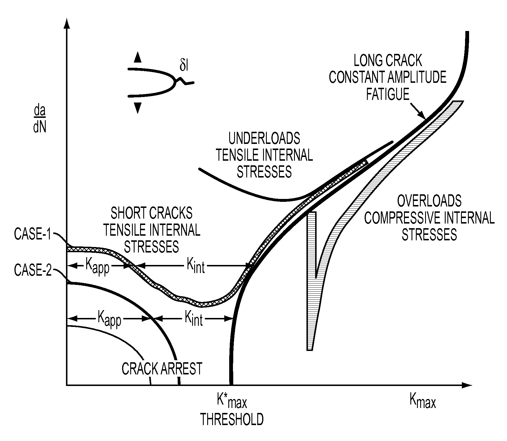
[0039]The invention is directed to a system and method for predicting component damage. In order to create a more reliable life prediction model for components, the basic physics of the problem are analyzed and a better approach is formulated in order to treat the overall damage as an intrinsic behavior of the material. This is accomplished by recognizing that: (1) the true material behavior is represented by the long crack growth properties, (2) fatigue damage must be described by two parameters, ΔKappl and Kmax,total instead of merely one (i.e. ΔK), and (3) the deviations from the long crack growth behavior arise from the internal stresses present ahead of the crack tip which contribute predominantly to Kmax. These internal stresses are either present in the material or generated ahead of the crack tip during overloads and underloads. The internal stresses can be tensile or compressive and are responsible for an accelerated growth in the short crack region, and decelerated growth ...


PUM

PropertyMeasurementUnit
crack lengthaaaaaaaaaa
grain sizeaaaaaaaaaa
crack growth rate da/dNaaaaaaaaaa

Abstract

A method and system for determining damage prediction of a component. The component may be critical component used in an aircraft or other vehicle experiencing cyclic loading. The method and system determines the ΔK, Kmax and Kinternal values for the component and utilizes these values in order to predict damage and / or failure of the component.

Description

CROSS-REFERENCE TO RELATED APPLICATIONS[0001]This Application is a non-provisional application of provisional (35 USC 119(e)) application 60 / 884,316 filed on Jan. 10, 2007, the entire disclosure of which is incorporated herein in its entirety.BACKGROUND[0002]1. Field of the Invention[0003]The field of the invention is related to methods and systems for predicting material fatigue and damage. In particular the invention relates to an improved method and system for applying an improved model of material fatigue and damage for a component design, maintenance and its life prediction.[0004]2. Description of the Related Technology[0005]The construction and maintenance of aircraft is a complex undertaking that can result in catastrophic effects if performed improperly. During the manufacture and usage of structural components of aircraft various defects can occur. Defects can occur during the manufacture and fabrication of components. Defects can also occur during the assembly, repair and ...

Claims


Application Information

Patent Timeline
Patent Type & Authority Patents(United States)
IPC IPC(8): G01N23/02
CPCB64F5/0045G07C3/14G01N2291/0231G01N2291/0258G01N2291/02827G01N2291/2694B64F5/60
Inventor VASUDEVAN, ASURI K.SADANANDA, KUNTIMADDIGLINKA, GRZEGORZKUJAWSKI, DANIEL
Owner NAVY SEC OF THE THE USA AS REPRESENTED BY THE
Why Eureka
Try Eureka