Rasp hub for tire retreading machine

a tire retreading machine and hub technology, which is applied in the field of tire retreading machines, can solve the problems of the precise positioning of the inner edges of the mounting apertures of the blade, and achieve the effect of enhancing the cutting radius and improving the concentricity

Inactive Publication Date: 2011-02-22
B&J ROCKET AMERICA INC
View PDF11 Cites 2 Cited by
  • Summary
  • Abstract
  • Description
  • Claims
  • Application Information

AI Technical Summary

Benefits of technology

[0014]The present invention improves the concentricity and thus the cutting operation of rasp blades mounted in stacks in a convex hub and enhances the conformance of the cutting radius of the blades to the true radius of the curvature of the cutting profile of the blade.
[0016]Further, it will be recalled that each blade has cutting teeth arranged to be offset laterally in alternate directions relative to the base plate of the rasp blade, each cutting edge being straight. Each blade of the present invention has two mounting apertures. The mounting apertures in each blade are elongated and slightly oversized relative to the diameter of the mounting pins. This permits the blades to be set at an angle relative to a perpendicular (or radial) plane to achieve a desired cut angle, while adjusting to the variations in position required due to the arrangement wherein the center planes of the curved mounting pins intersect, preferably, in proximity to the axis of rotation of the hub.
[0017]Further, the present invention provides for a more uniform location of all blades in all stacks relative to the axis of rotation by providing in each blade, that the innermost edge of each oblong mounting aperture is generally straight and extends tangentially to a circle centered on the axis of rotation. This tangential edge forms a locating edge for the blade under centrifugal force, and provides a more precise positioning of the blades, even though the contact point between the locating edge of the mounting aperture and the mounting pin changes for adjacent blades due to the curvature and angled positioning of the mounting pins, and the placement of the blades at different lengthwise locations along the curved central portion of the mounting pins. By this means, as the hub is rotated at cutting speed, centrifugal force urges the blades to edge outwardly. However, the precision locating inner edges of the mounting apertures of the blade engages, and is limited by the mounting pin of the hub which limits this radial outward migration of the blade caused by centrifugal force and accurately locates each blade in the desired location relative to the other blades, and precisely sets the cutting edge for ill blades in a section or stack which is repeated stack-to-stack.
[0018]Moreover, the cutting edges have a more accurate location relative to a cut profile of uniform radius. That is, the small cutting edges of all blades, whether in the center of the stack or on the side, are more uniformly aligned with the curvature of the desired cut profile.
[0020]Further, in regard to the hub design—in particular, the blade inclination relative to a plane perpendicular to the axis of rotation of the hub—one embodiment of the invention combines the previous “sawtooth” configuration for some adjacent stacks, with at least one “chevron” arrangement provided by two adjacent stacks, thereby providing both a rapid rate of material removal and improved surface texture.

Problems solved by technology

However, the precision locating inner edges of the mounting apertures of the blade engages, and is limited by the mounting pin of the hub which limits this radial outward migration of the blade caused by centrifugal force and accurately locates each blade in the desired location relative to the other blades, and precisely sets the cutting edge for ill blades in a section or stack which is repeated stack-to-stack.

Method used


Image

  • Rasp hub for tire retreading machine
  • Rasp hub for tire retreading machine
  • Rasp hub for tire retreading machine

Examples


Embodiment Construction

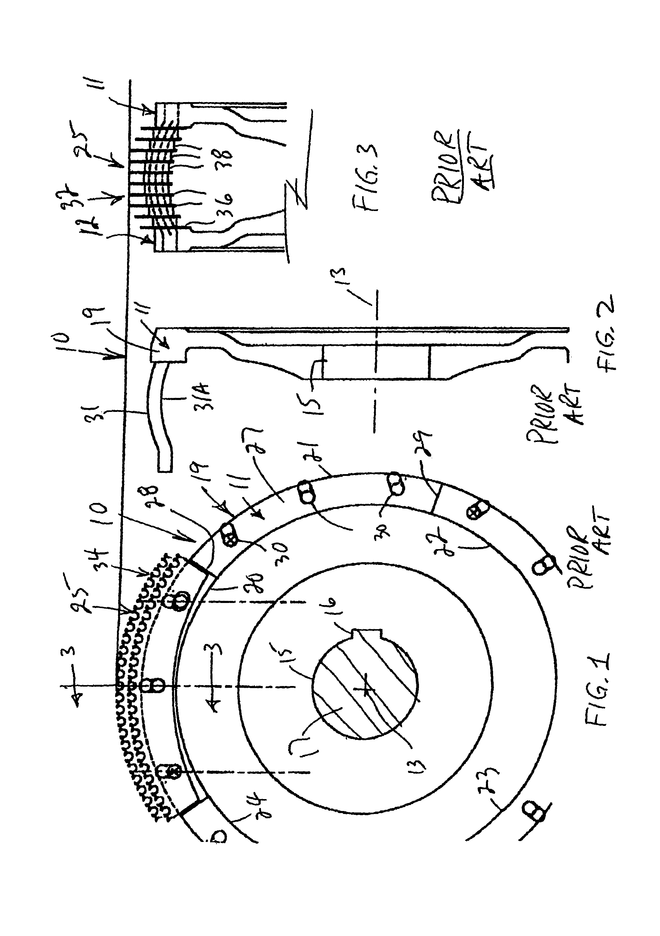
[0032]Reference numeral 10 generally designates a hub for use in retreading tires. The hub 10 includes first and second end plates 11, 12 (FIG. 3), sometimes referred to as mounting plates. The mounting plates 11, 12 are sometimes referred to, by convention, as the pinside and top side mounting plates. This convention derives from the fact that typically a retreading hub is mounted for rotation about a vertical axis, whereas, in FIGS. 1 and 3, the axis of the hub (indicated by the chain line 13 in FIG. 2) is horizontal. The pins are pressed into the pinside mounting plate and slidably received in the topside mounting plate to facilitate blade replacement.

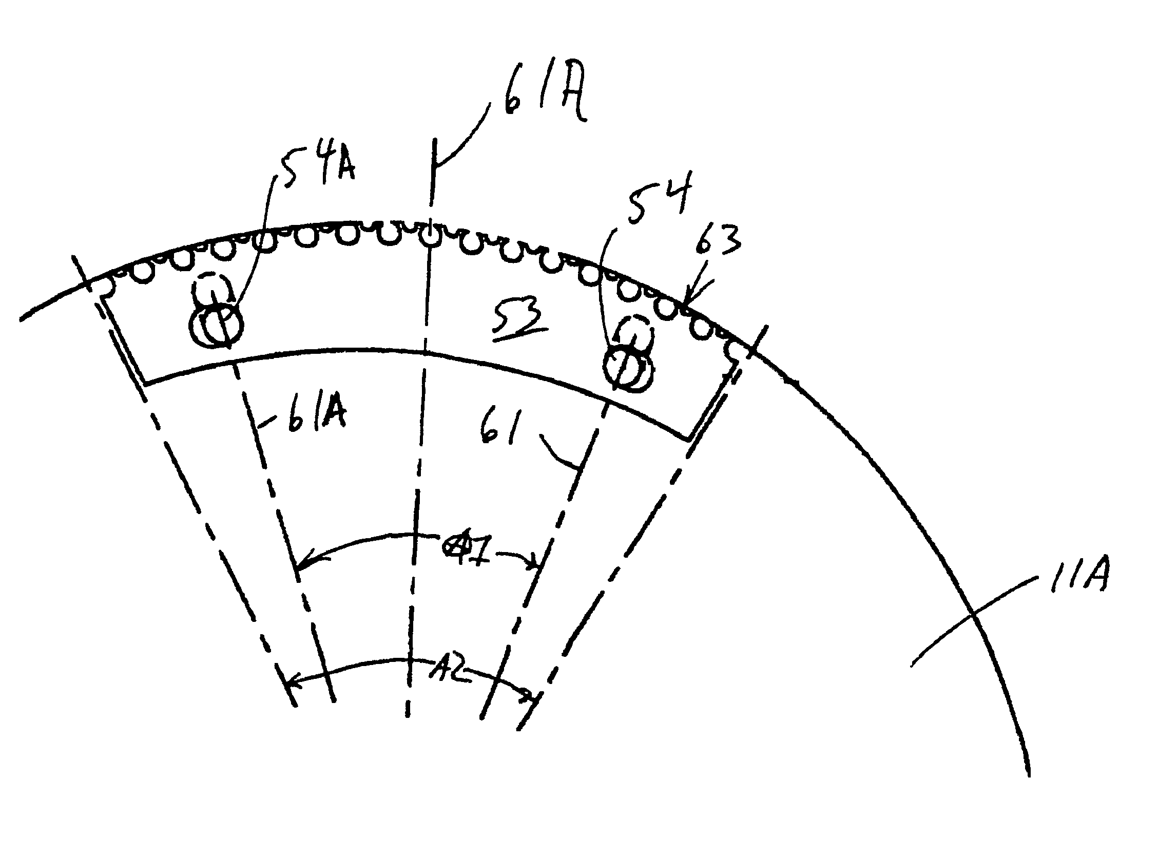
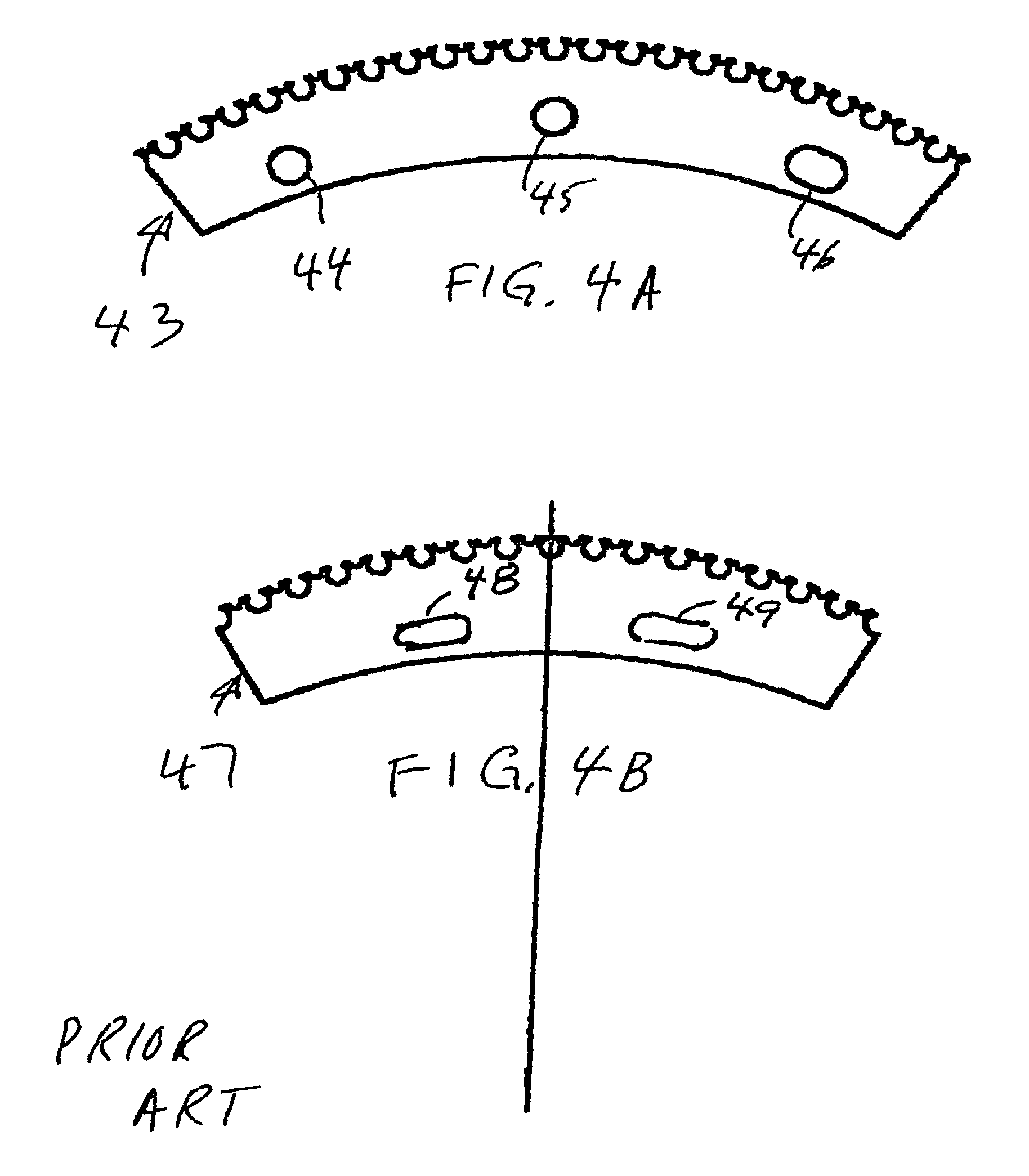
[0033]The hub plate 11 includes a circumferential flange 19 which is divided into a series of sections extending circumferentially about the periphery of the hub, each corresponding to a stack or section of blades. In the illustrated embodiment of FIGS. 1-3, there are five such peripheral segments, designated respectively 20, 21, 22...


PUM

PropertyMeasurementUnit
included angleaaaaaaaaaa
cut angleaaaaaaaaaa
cut anglesaaaaaaaaaa

Abstract

A rasp hub for use in tire retreading machines includes two side plates with mounting pins extending between the plates. Rasp blades arranged in stacks are mounted on the mounting pins. The stacks extend end-to-end circumferentially about the hub. The center portion of the mounting pins is curved so that the cut profile of the blades is convex. The blades are inclined relative to a plane perpendicular to the axis of rotation to define a cut angle. The center planes of the mounting pins intersect, preferably close to the axis of rotation of the hub, to reduce deviation of the blades from the concentricity.

Description

RELATED APPLICATION[0001]This application claims benefit under 35 U.S.C. 120 of U.S. Application No. 60 / 756,685 filed Jan. 6, 2006 for “RASP HUB FOR TIRE RETREADING MACHINE”.FIELD OF THE INVENTION[0002]The present invention relates to tire retreading machines; and in particular to improvements in tire retreading machine hubs for of the type known as convex hubs.BACKGROUND OF THE INVENTION[0003]Tire retreading machines, commonly referred to as buffers, are used in the process of retreading tires to remove the existing tread surface from a tire, to prepare the remaining surface by cutting, and to buff the receiving surface to promote better adhesion prior to applying a new tread.[0004]Typical tire retreading buffers include a rasp, which typically may be comprised of two mounting plates referred to as a pinside and a topside plate respectively. It is further comprised of locating or mounting pins extending between the hub mounting plates. One end of each mounting pin may be fixed to t...

Claims


Application Information

Patent Timeline
Patent Type & Authority Patents(United States)
IPC IPC(8): B23D71/00B26D1/00
CPCB23D71/025B29B17/02B29B2017/044B29D2030/541Y10T407/181Y02W30/521Y02W30/625Y02W30/622Y10T407/1825B29L2030/00Y02W30/52Y02W30/62
Inventor STANFIELD, CHARLES K.
Owner B&J ROCKET AMERICA INC
Why Eureka
Try Eureka