Generator circuit breaker with improved switching capacity

a generator circuit and switching capacity technology, applied in the direction of air-break switches, high-tension/heavy-dress switches, electrical apparatus, etc., can solve the problems of large expansion of the outlet-flow path, laminar flow, and enlarge the cooling surface area of the exhaust, so as to improve the cooling of the switching gas, improve the cooling effect, and the effect of excellent disconnection ratings

Active Publication Date: 2011-02-22
HITACHI ENERGY LTD
View PDF24 Cites 14 Cited by
  • Summary
  • Abstract
  • Description
  • Claims
  • Application Information

AI Technical Summary

Benefits of technology

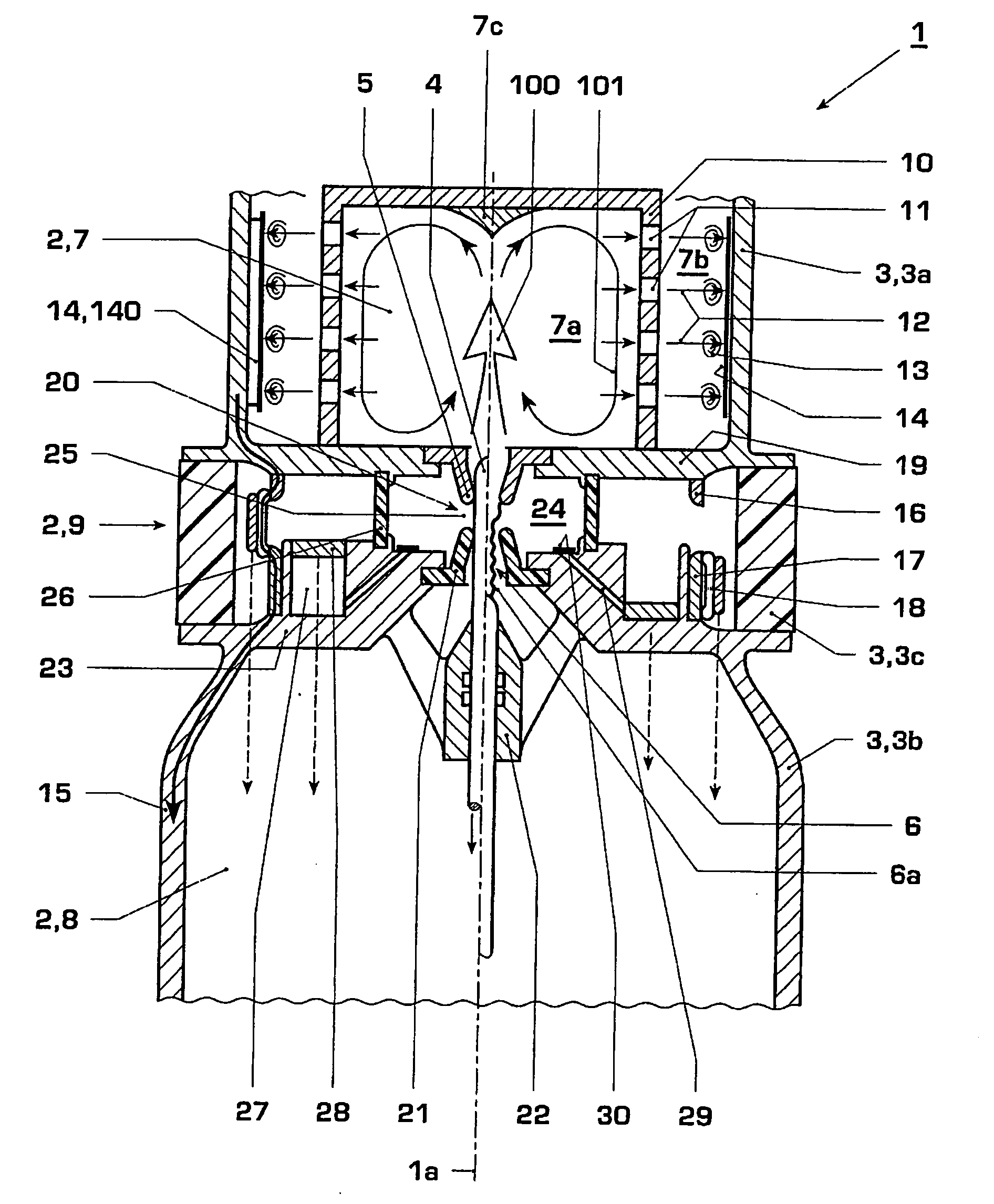
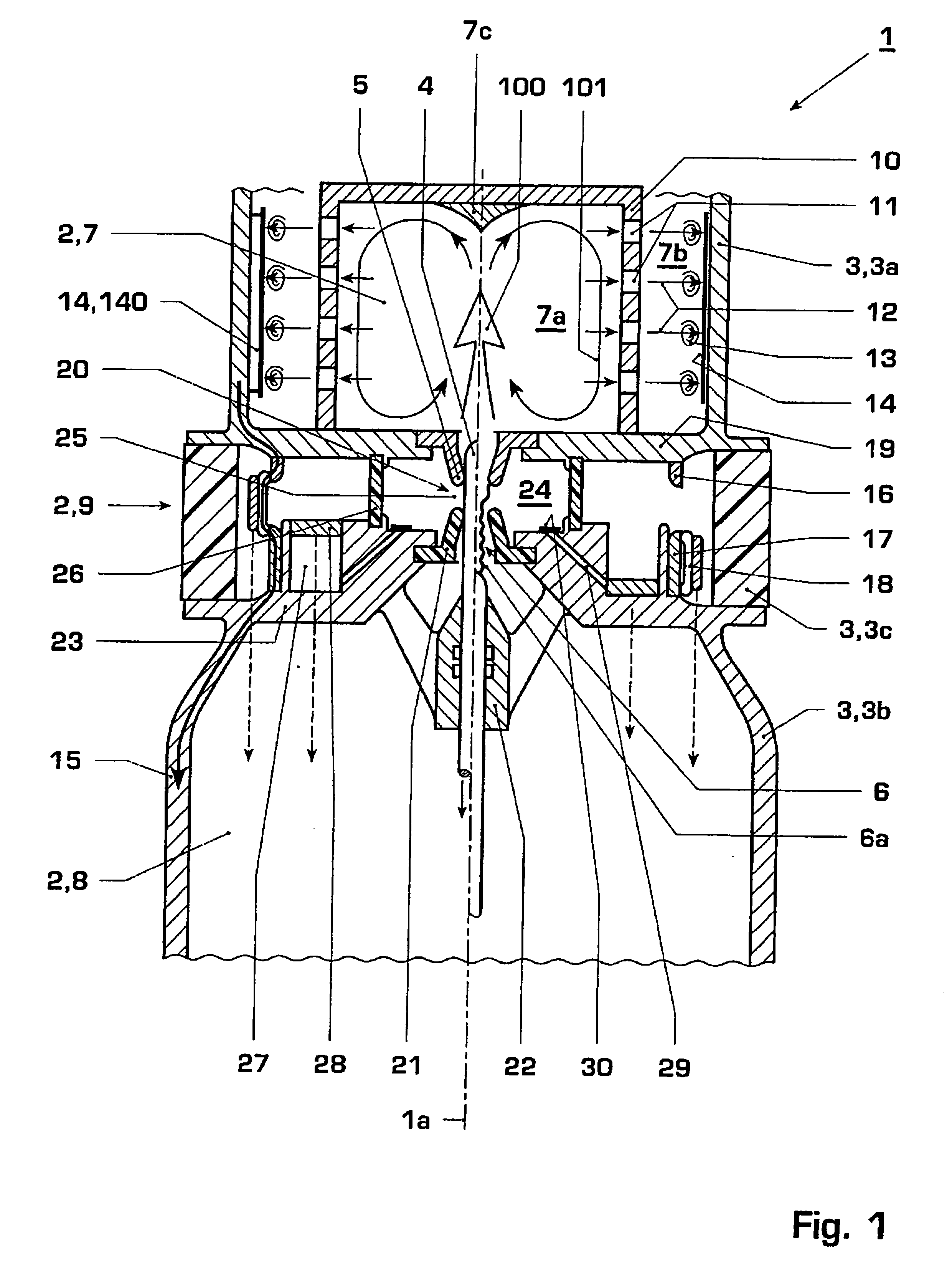
[0010]An exemplary embodiment can have the advantage that no electrical flashovers between the switching gas and the baffle wall are expected, because there is no or no significant potential gradient in the outer volume through which the switching gas flows. Even still highly ionized switching gas, which has not yet dielectrically recovered, can be cooled on the baffle wall, which is on a live potential.
[0019]Other exemplary embodiments as disclosed can relate to further measures for improving the cooling efficiency of the switching gas in the switching device and thus for increasing the switching rating.

Problems solved by technology

This arrangement therefore substantially lengthens the outlet-flow path, and enlarges the cooling surface area in the exhaust.
In addition, a dielectric body is provided, is located further inward, does not allow quenching gas to pass through, shields the metal body from the quenching gases, precools the quenching gases by material vaporization, and thus counteracts overheating of the metal wire mesh.
Owing to the large number of aperture openings, the flow resistance of the metal wire mesh is low, again resulting in laminar flow.

Method used


Image

  • Generator circuit breaker with improved switching capacity
  • Generator circuit breaker with improved switching capacity
  • Generator circuit breaker with improved switching capacity

Examples


Embodiment Construction

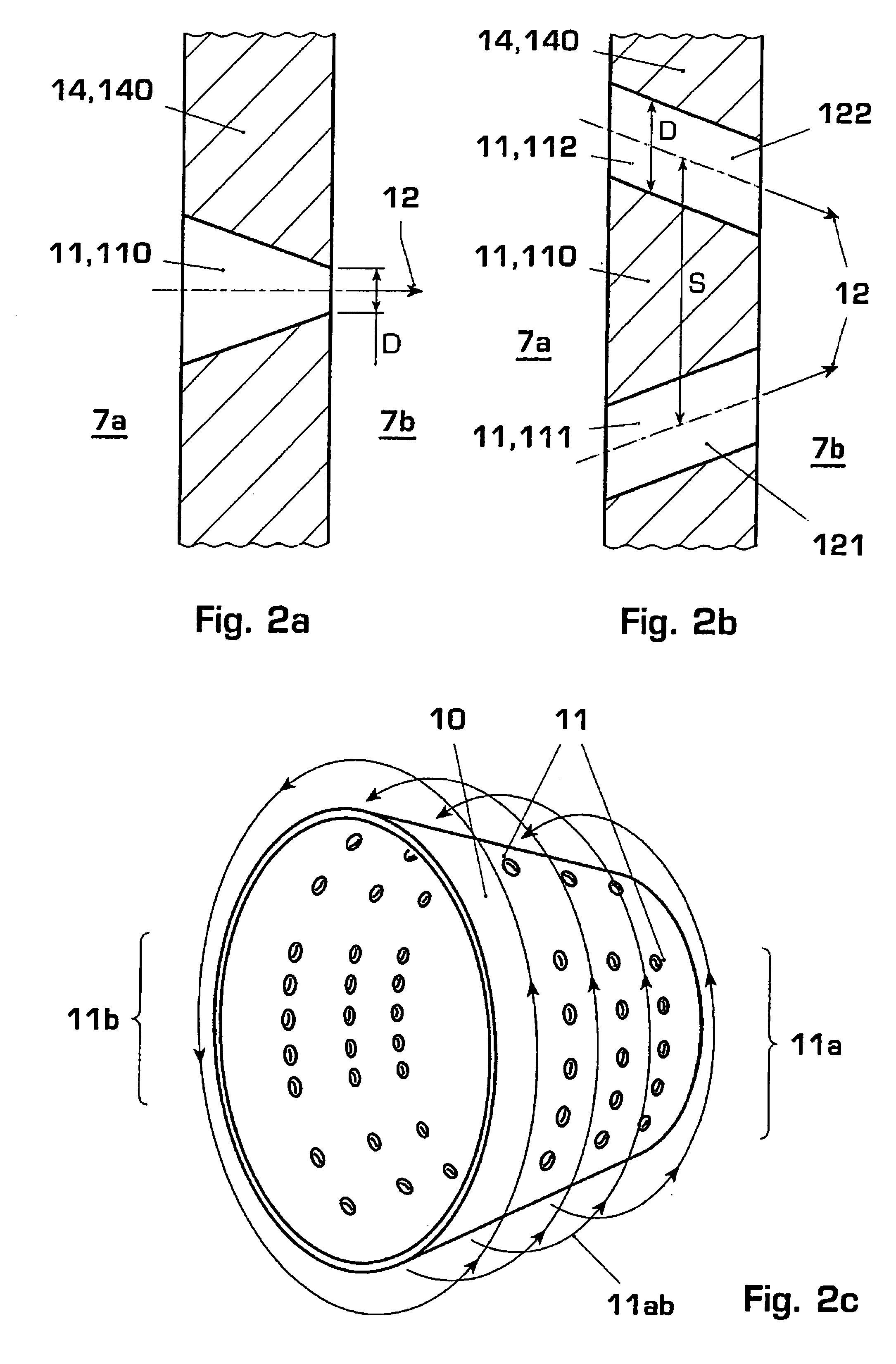
[0027]FIG. 1 shows a generator circuit breaker 1 with a circuit breaker axis 1a and a switching chamber 2 or interrupter unit 2, which comprises a quenching chamber 9 and exhaust volumes 7, 8. The switching chamber 2 is surrounded by a switching chamber enclosure 3. The switching chamber enclosure 3 is composed of a quenching chamber enclosure or quenching chamber isolator 3c and a first exhaust enclosure 3a and a second exhaust enclosure 3b. A first contact or contact pin 4 and a second contact in the form of a contact tulip 5, between which an arc 6a is struck on opening of the circuit breaker 1, are provided for the power current path and for arc interruption. The basic operation of the switching device 1 is described in EP 0 982 748 B1, whose entire disclosure content is hereby included by reference in the description. In particular, the functions of the switching device 1 are described there. The reference symbols denote the following components: rated current path 15, first st...


PUM


Abstract

The disclosure relates to an electrical switching device, e.g., a generator circuit breaker, and to a method for improved switching-gas cooling. Gas jets are formed by a nozzle body in the exhaust area, are directed against a baffle wall and are swirled. The baffle wall is a component of the switching chamber enclosure and has a high thermal capacity and / or thermal conductivity, so that the switching gas vortices produce a highly efficient switching gas cooling on the baffle wall by turbulent convection. Exemplary embodiments relate inter alia to the design of the baffle wall and of the nozzle body. Advantages include: protection of the switching chamber enclosure against hot gases, improved switching gas cooling, and increased breaking capacity.

Description

RELATED APPLICATIONS[0001]This application is a continuation application under 35 U.S.C. §120 to PCT / CH2004 / 000752 filed as an International Application on Dec. 24, 2004, designating the U.S., the entire contents of which are hereby incorporated by reference in their entireties.TECHNICAL FIELD[0002]The disclosure relates to the field of high-voltage technology, e.g., high-current circuit breaker technology in electrical power distribution systems. It is based on a method and generator circuit breaker.BACKGROUND INFORMATION[0003]The disclosure is based on the prior art according to EP 1 403 891 A1, which discloses a circuit breaker in which exhaust gas from an arcing area is passed through a hollow contact into a concentrically arranged exhaust volume, and from there into a quenching chamber volume located further outward. In order to increase the disconnection rating, at least one intermediate volume and, possibly, an additional volume is or are arranged concentrically between the h...

Claims


Application Information

Patent Timeline
Patent Type & Authority Patents(United States)
IPC IPC(8): H01H33/91
CPCH01H33/74H01H33/88H01H2009/526H01H2033/888
Inventor SCHOENEMANN, THOMASKIEFER, JOCHENHUGUENOT, PATRICKCLAESSENS, MAXGROB, STEPHANYE, XIANGYANG
Owner HITACHI ENERGY LTD
Why Eureka
Try Eureka