
Transmission bearing noise attenuation device

Inactive Publication Date: 2011-03-01
SCHAEFFLER TECH AG & CO KG
View PDF10 Cites 0 Cited by
  • Summary
  • Abstract
  • Description
  • Claims
  • Application Information

AI Technical Summary

Benefits of technology

[0012]The cam ring is provided, on the inside and outside, with support protuberances or cams, which are brought into contact, with a certain amount of play, with the outer surface and / or the inner surface. The height of the cams or the support protuberances is identical. That results under operating conditions in a reduced shaft offset, whereby the bearing application area of the bearing isolation is significantly increased. In addition, that solution, involving a cam ring, makes possible more economical manufacturing.
[0027]The cam ring can be produced by stamping and subsequent bending, which is extremely advantageous for economical manufacturing.
[0028]A further advantage for economical manufacturing is when a cam ring is composed of rectangular or round wire material.
[0029]In addition, it is advantageous for the support protuberances to be produced having an exact size by means of a transverse impact extrusion process.

Problems solved by technology

However, internal combustion engines and other power train components, such as transmissions, do create noises that can generally be perceived as constituting a disturbance.
In continuously variable transmissions, the use of a plate-link chain can lead to the production of noise, because a plate-link chain, by virtue of its structure with links and pins, creates a repetitive knocking noise during operation of the transmission when the pins strike the conical disks of the transmission.
However, they have the disadvantage that as a result of their spring deflection, a displacement of the shaft as a function of the load is induced.
That can lead on the one hand to loads that are so great as to damage components in contact with it, and on the other hand to an increase in noise production.
An additional disadvantage is the fact that the cam height on the inner radius and the perimeter of such radially-undulating springs are different.
The addition of the tolerances is superimposed on the load-dependent displacement resulting from the spring deflection as a static positioning error, whereby the total tolerance in the position of the shaft relative to the housing becomes very large.

Method used


Image

  • Transmission bearing noise attenuation device
  • Transmission bearing noise attenuation device
  • Transmission bearing noise attenuation device

Examples


Embodiment Construction

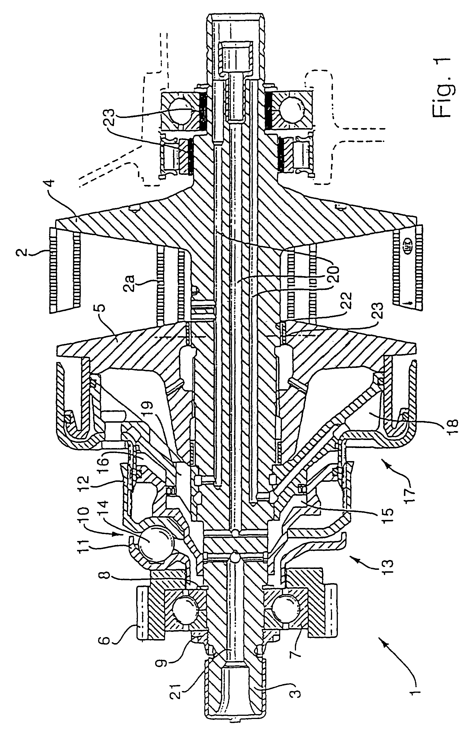
[0041]FIG. 1 shows only one part of a belt-driven conical-pulley transmission, specifically the part of the belt-driven conical-pulley transmission 1 that is driven by a drive motor, such as an internal combustion engine, and is located on the drive side or the input side. In a completely implemented belt-driven conical-pulley transmission, the input side part is associated with a complementary output side part of the continuously-variable, belt-driven conical-pulley transmission, whereby both parts are connected to each other by means of an endless torque-transmitting means, for example in the form of a plate-link chain 2 for transmitting torque. The belt-driven conical-pulley transmission 1 has a shaft 3on the input side thereof, which, in the design shown is integrally formed with a fixed conical pulley 4. This axially-fixed conical pulley 4 is adjacent, in the axial longitudinal direction of the shaft 3, to an axially-displaceable conical pulley 5.

[0042]In the representation acc...


PUM


Abstract

A transmission noise attenuation device for a bearing assembly of a belt-driven conical-pulley transmission having a chain that serves as an endless torque-transmitting device. A shaft is rotatably supported in a bearing that includes a bearing outer ring with a cylindrical outer surface, wherein the bearing is supported in a bearing housing. At least one cam ring is positioned between the bearing housing inner surface and the bearing outer ring outer surface. The cam ring is elastically deformable to allow limited radial movement between the bearing housing inner surface and the bearing outer ring outer surface.

Description

BACKGROUND OF THE INVENTION[0001]1. Field of the Invention[0002]The present invention relates to a belt-driven conical-pulley transmission, such as a continuously variable transmission, having an endless torque-transmitting means in the form of a drive chain, as well as to a noise attenuation device for a shaft bearing supported in a bearing housing. The invention also relates to a cam ring structure for a noise attenuation arrangement.[0003]2. Description of the Related Art[0004]The requirement for comfort in automobiles is generally very high, also particularly with regard to acoustics. Especially for luxury automobiles, the driver and passengers wish to prevent any disturbing noise originating as a result of operation of the automobile power train. However, internal combustion engines and other power train components, such as transmissions, do create noises that can generally be perceived as constituting a disturbance. In continuously variable transmissions, the use of a plate-li...

Claims


Application Information

Patent Timeline
IPC IPC(8): F16H55/56F16C27/06F16C27/04F16H9/12F16H55/36F16H57/00
CPCF16C27/04F16H55/56F16H57/0006F16C19/06F16C35/077F16C2361/63F16C2361/65
Inventor GLAS, RONALD
Owner SCHAEFFLER TECH AG & CO KG
Features
  • Generate Ideas
  • Intellectual Property
  • Life Sciences
  • Materials
  • Tech Scout
  • Unparalleled Data Quality
  • Higher Quality Content
  • 60% Fewer Hallucinations
Learn More