Piezoelectric cascade resonant lamp-ignition circuit

a cascade resonant and cascade technology, applied in the direction of electric ignition installation, mechanical equipment, machines/engines, etc., can solve the problems of low efficiency and low breakdown voltage of traditional coil-type step-up transformers, low design efficiency, and large leakage current, and achieve high lamp ignition efficiency and small leakage current

Active Publication Date: 2011-03-08
MIDAS WEI TRADING +1
View PDF5 Cites 4 Cited by
  • Summary
  • Abstract
  • Description
  • Claims
  • Application Information

AI Technical Summary

Benefits of technology

[0007]The primary objective of the present invention is to provide a piezoelectric cascade resonant lamp-ignition circuit, which uses the intrinsic capacitors of a piezoelectric transformer as piezoelectric capacitors, wherein several sets of the piezoelectric capacitors and a resonant inductor are cascaded to form a resonant lamp-ignition circuit, whereby the lamp-ignition circuit of the present invention has advantages of small leakage current, current balance and high lamp ignition efficiency.
[0008]Another objective of the present invention is to provide a piezoelectric cascade resonant lamp-ignition circuit, wherein a piezoelectric transformer replaces the capacitors of the traditional lamp-ignition circuits or the coil-type step-up transformers, whereby the present invention has small volume and outstanding electric performance, and whereby the present invention prevents from overheat and malfunction caused by low breakdown voltage, wherefore the present invention has high reliability and superior market competitiveness.
[0009]A further objective of the present invention is to provide a piezoelectric cascade resonant lamp-ignition circuit, which uses cascade connection to decrease wire length and reduce the final size of the product.
[0010]To achieve the abovementioned objectives, the present invention replaces the ballast and inverter of the conventional resonant lamp-ignition circuit with a piezoelectric capacitor, which is originally used as the high-power piezoelectric ceramic oscillation plate of the ultrasonic oscillator. The resonant lamp-ignition circuit of the present invention has a step-up ratio varying with the inner impedance of the load; therefore, the present invention is very suitable to drive lamps. When lamps have not lightened yet, the equivalent circuit is in an open-circuit state, and the resonant lamp-ignition circuit of the present invention supplies a very high step-up ratio to instantly ignite the lamps. When the lamps have lightened, the equivalent impedance and the step-up ratio both decrease, and the lamps operate in a steady state.

Problems solved by technology

However, the traditional coil-type step-up transformer has low efficiency and low breakdown voltage.
Therefore, the traditional coil-type step-up transformer is an unsafe device because it is likely to be punctured by a high voltage and burned down.
However, such a design has low efficiency and great leakage current.
Further, the capacitor 110 has low breakdown voltage and may explode and cause a fire.

Method used


Image

  • Piezoelectric cascade resonant lamp-ignition circuit
  • Piezoelectric cascade resonant lamp-ignition circuit
  • Piezoelectric cascade resonant lamp-ignition circuit

Examples


Embodiment Construction

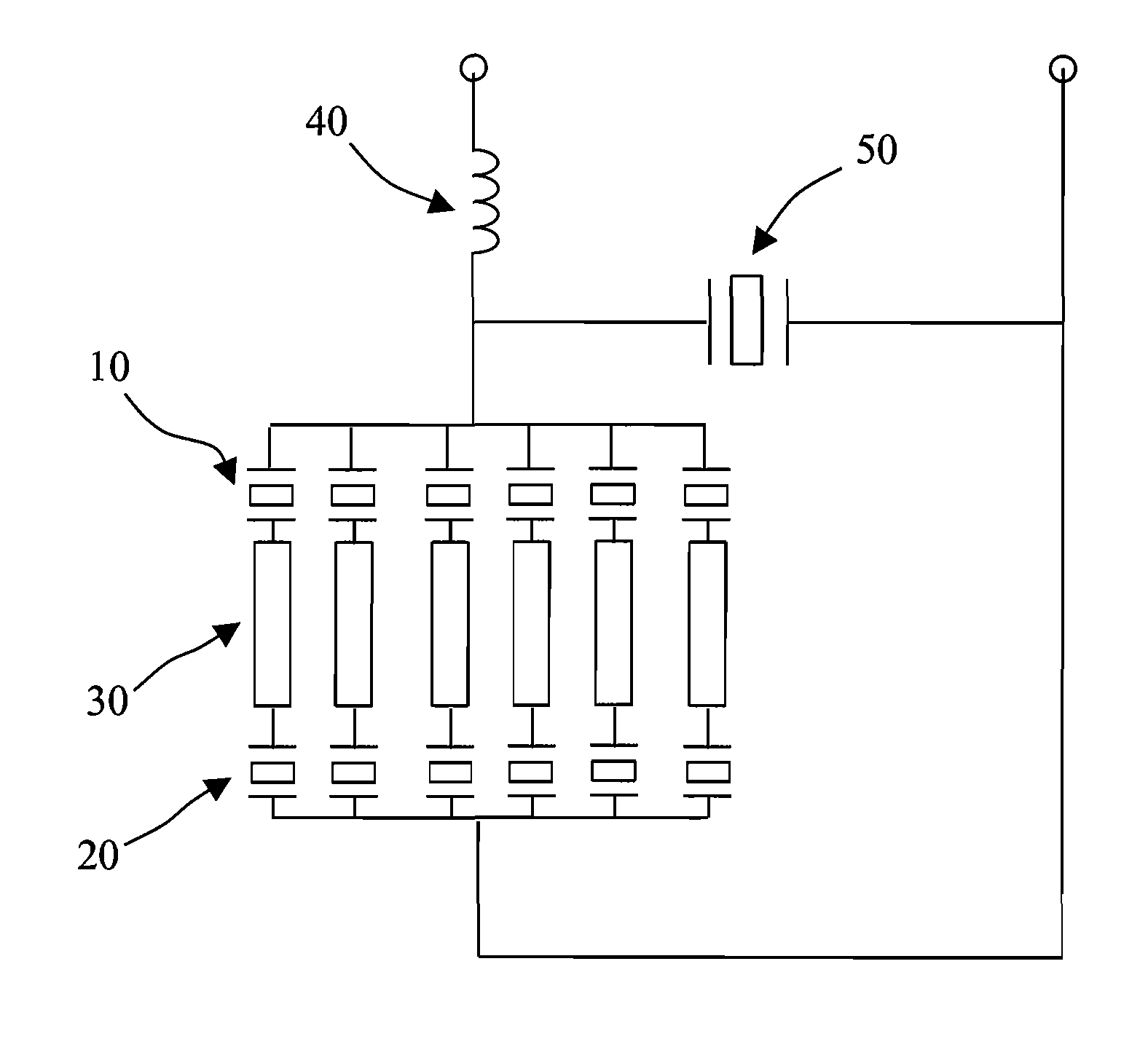
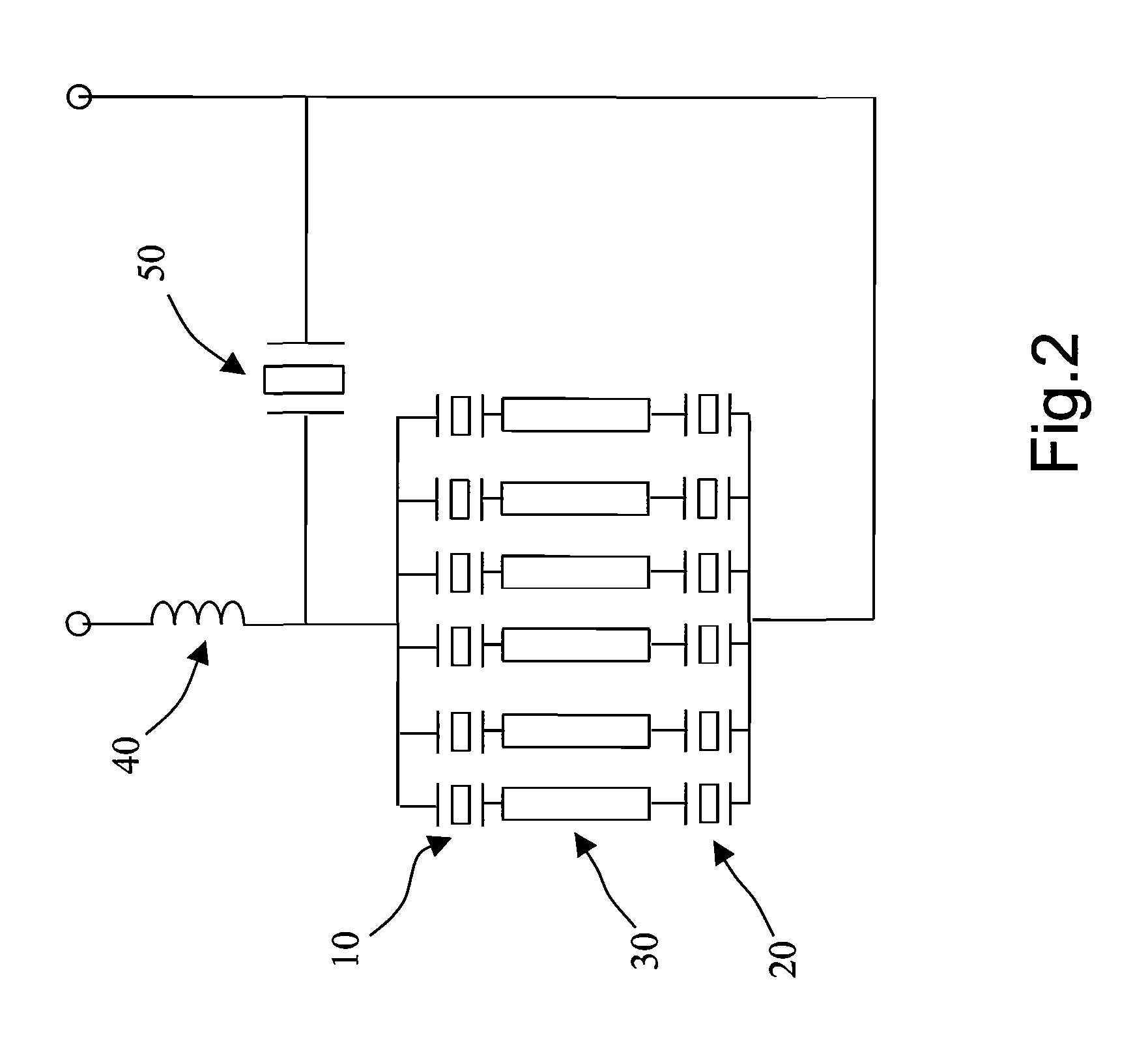
[0024]Refer to FIG. 2 a diagram schematically showing a piezoelectric cascade resonant lamp-ignition circuit according to one embodiment of the present invention. As shown in FIG. 2, the lamp-ignition circuit of the present invention comprises several sets of piezoelectric capacitors 10 and 20 and a resonant inductor 40. Each set of piezoelectric capacitors 10 and 20 are cascaded to a CCFL 30. All sets of piezoelectric capacitors 10 and 20 are parallel connected, and then all sets of piezoelectric capacitors 10 and 20 are totally cascaded to the resonant inductor 40. In the present invention, the intrinsic capacitors of the piezoelectric transformer function as the piezoelectric capacitors 10 and 20. The piezoelectric capacitors 10 and 20 and the resonant inductor 40 are cascaded to form a resonant lamp-ignition circuit containing an inductor and a piezoelectric transformer cascaded to each other. The resonant lamp-ignition circuit is boosted to ignite lamps by adjusting the resonan...


PUM


Abstract

The present invention discloses a piezoelectric cascade resonant lamp-ignition circuit, which uses the intrinsic capacitors of a piezoelectric transformer as piezoelectric capacitors. One lamp is cascaded to one set of the piezoelectric capacitors. Several sets of the piezoelectric capacitors and a resonant inductor are cascaded to form a resonant lamp-ignition circuit. The lamp-ignition circuit of the present invention has advantages of low temperature, small leakage current, high breakdown voltage and high lamp ignition efficiency. When applied to drive several lamps, the present invention uses a fixed frequency to attain a fixed inner impedance of the equivalent circuit of the piezoelectric capacitor. Thereby, the currents of the lamps are balanced to have an identical value.

Description

[0001]The present invention is a continuous-in-part application of the application that is entitled “HIGH-VOLTAGE LAMP-IGNITION PIEZOELECTRIC OSCILLATOR” (U.S. application Ser. No. 12 / 025,852) filed Feb. 5, 2008 now U.S. Pat. No. 7,683,554, which is filed presently with the U.S. Patent & Trademark Office, and which is used herein for reference in its entirety.BACKGROUND OF THE INVENTION[0002]1. Field of the Invention[0003]The present invention relates to a cascade resonant lamp-ignition circuit, particularly to a piezoelectric cascade resonant lamp-ignition circuit formed via cascading several sets of piezoelectric capacitors to an independent inductor.[0004]2. Description of the Related Art[0005]The principle of CCFL (Cold Cathode Fluorescent Lamp) is similar to that of the daylight lamp. When a high voltage is input to the electrodes, few electrons impact the electrode at high speed to generate secondary electrons. Then, discharge begins, and electrons collide with mercury atoms, ...

Claims


Application Information

Patent Timeline
Patent Type & Authority Patents(United States)
IPC IPC(8): H05B41/00H05B44/00
CPCH05B41/2827
Inventor WEI, TAO-CHINCHOU, MING SHINGCHANG, HSI CHEN
Owner MIDAS WEI TRADING
Why Eureka
Try Eureka